Home BOM PS LO DIV Op-Amp RF Mixer Connect
IV – Softrock Lite V6.2 – OpAmps
Parts
|
Designation |
Description |
Type
Component |
Quantity |
|
U5 |
TVL2462CD |
SMT OpAmp IC |
1 |
|
C11, C13 |
0.047uF |
Ceramic Capacitor |
2 |
|
C12, C14 |
1500 pF |
Ceramic Capacitor |
2 |
|
C15, C16, C17, C19 |
0.1 uF |
SMT Capacitor |
5 |
|
C18 |
10 uF |
Electrolytic Cap |
1 |
|
undesignated |
5uF |
Coupling cap for test |
1 |
|
R10, R12 |
10 Ohm |
¼ W 1% |
2 |
|
R11, R13, R14, R15 |
1 k Ohm |
¼ W 1% (brown black red brown) |
5 |
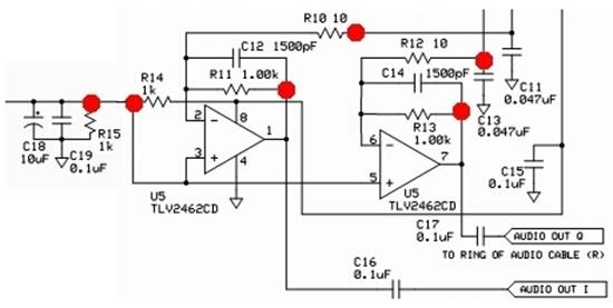
Schematic
Installation Notes
This involves installing another SMT IC (see the hints in the Dividers Section).
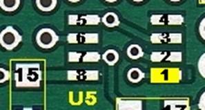
OpAmp IC (U5)

Electro Static Discharge precautions (e.g., anti-static mat, anti-static wrist-strap, grounded tip soldering iron) must be taken when handling/installing these ICs
See the excellent video tutorials on SMT soldering at Sparkfun.com and KC0WOX’s video (Surface Mount Soldering IC's).
The ICs in the kit are such that if an IC provided in the kit fits an IC mounting location on the circuit board, then the IC is right for that location.
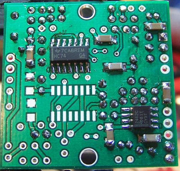
Orient U5 on its pads so that the pin 1 corner of the IC matches the small “1" (it also looks like a “0”) mark in the copper on the bottom side of the board. In general, pin 1 of an SOIC packaged IC is in the lower left corner of the package when the printing on the package top reads upright, from left to right.
Tack-solder one corner pin of U5 and reheat the tacked pin as necessary to line up U5 on its pads properly.
Double-check the orientation of U5 and the line up of the IC on its pads with magnification and good lighting. You do NOT want to install U5 oriented incorrectly. If all is well, carefully solder the rest of the leads to their pads.
SMT Caps (Topside)
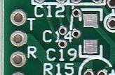
The SMT Cap, C19, is installed on the top side of the board.
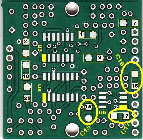
SMT Caps (Bottomside)
Three of the .01 uF SMT Caps (C15, C16, and C17) are installed on the bottom side of the board along with the IC U5.
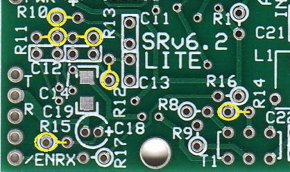
Ceramic Caps
Next, install ceramic capacitors C11-C14 on the top side of the board, and then install C18 (being careful to match the polarity correctly – the long lead is the positive lead).
c C11 0.047uF ceramic
c C12 1500 pF ceramic
c C13 0.047uF ceramic
c C14 1500 pF ceramic
Electrolytic Cap (C18)
c C18 is installed with attention paid to ensuring the positive lead (the longest lead) goes to the positive (“+”) hole.
Resistors
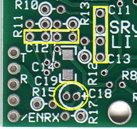
Finally, install the five resistors (R10-R14) on the top side of the board. Note that R14 and R16 could be confused: R14 lies below R16:
c R10 (west-east): 10 Ohms
c R11 (east-west): 1 k Ohm
c R12 (south-north): 10 Ohms
c R13 (east-west): 1 k Ohm
c R14 (west-east): 1 k Ohm
c R15 (west-east): 1 k Ohm
Tests
Current Draw
Current draw should be on the order of 28.1 mA (Author’s completed stage drew 28.1 mA)
Voltage Tests
R14 and R15 provide a voltage divider to yield the 2.5 VDc bias for the Op-Amps. You should see ~2.5 Vdc at the hairpin of R14 or R15. Author got 2.48 Vdc.
Op-Amp Function Test
You can test the functioning of both of the op-amps by comparing the pin-out voltages under different input resistance measurements. The test requires you to have a 1.5 k Ohm to 3.3 k Ohm resistor (of any wattage or precision) that you can temporarily connect to the circuit. The author used an available 2.2 k Ohm resistor.
c Power up the circuit and measure the voltage at pin 1 of the op-amp (hairpin of R11). It should be ~2.5 Vdc
c Power off and use clip leads to connect a 2.2 k Ohm resistor (Rt ) between the hairpin of R10 and circuit ground. (This provides an input resistance Ri) of 2210 ohms to the op-amp.
c Power up and measure the voltage at the hairpin of R11. You should get ~3..74 Vdc1. Remove Rt and the output voltage should go back to ~2.5 Vdc.
c Perform the same test for op-amp 2, substituting R12 for R10 and R13 for R11
|
Test Condition |
Rt |
Expected
Eout |
Author’s
Eout |
Measured
Eout |
|
Normal: Pin 1 (R11 hairpin) |
Not connected |
2.5 Vdc |
2.48 |
|
|
Bridged: Pin 1 (R11 hairpin) |
2200 ohms |
3.63 Vdc |
3.60 |
|
|
Normal: Pin 7 (R13 hairpin) |
Not connected |
2.5 Vdc |
2.48 |
|
|
Bridged: Pin 7 (R13 hairpin) |
2200 ohms |
3.63 Vdc |
3.60 |
|
1. Normally, the inverting (“-“) input of the op-amp is at the bias level set by the voltage divider, R14/R15 (~2.5 Vdc). With no input, the output will be held at the same as the bias voltage. Connecting Rt to ground causes a current to flow at the inverting input. Using ohms law, we can derive that current as Ebias / (Rt + R10) or 2.5/(2200+10) = 1.24 mA. This current will also flow in R11, the feedback resistor, and will result in a voltage that, when added to the bias voltage at the output of the op-amp, is the op-amp’s output voltage, Eout. The formula for determining this with a test resistor (Rt) of your choice is:
Eout = Ebias + [ R11 * Ebias / (Rt + R10) ]
= 2.5 + [1000 * 2.5 / (2200 + 10) ]
= 2.5 + [1000 * .001131]
= 2.5 + 1.244 = 3.631 Vdc
An Excel spreadsheet with a calculator for this test is available for you to plug in your Rt and Ebias and predict the Eout
IC Pin Voltages
In addition to using the convenient test points indicated in the table below, you should also double check by measuring the voltages on the actual IC pins (to detect the case of a poor or missing solder joint between the pin and the pad.
|
Test
Point |
Expected
Value |
Units |
Author
Results |
Measured
Value |
|
U5-1 (R11 hairpin) |
2.5 |
vdc |
2.48 |
|
|
U5-2 (R10 hairpin) |
2.5 |
vdc |
2.48 |
|
|
U5-3 (R14 hairpin) |
2.5 |
vdc |
2.48 |
|
|
U5-4 (GND) |
0 |
vdc |
0 |
|
|
U5-5 (R14 hairpin – voltage divider) |
2.5 |
vdc |
2.48 |
|
|
U5-6 (R12 hairpin) |
2.5 |
vdc |
2.48 |
|
|
U5-7(R13 hairpin) |
2.5 |
vdc |
2.48 |
|
|
U5-8 |
5 |
vdc |
4.94 |
|
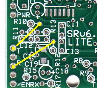
Audio Injection
Once the Op Amps are installed, we can run a simple test by injecting a low-level 1 kHz audio tone into the inputs (the hairpin leads of R10 and R12) and checking for signal and strength at the I and Q outputs.
Be sure to use a DC blocking capacitor of around 5 uF or the signal generator will change the op amp bias and you will have no output.
Connect a signal generator at 10 mV amplitude through a ~5uF coupling capacitor to the above test points. The frequency isn't particularly critical as the receiver will output signals in the 1 - 100kHz frequency range. The voltage isn't either as long as you don't get too large. You should see an amplification factor of about 40 to 1.
As an alternative to using a scope, you can connect the ring and tip outputs to your sound card’s stereo inputs, download, install, and run Rocky, and view the signal on Rocky’s spectrum view.
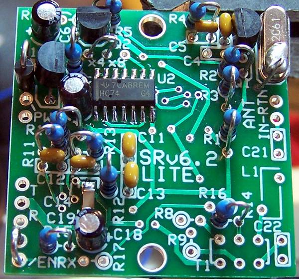
Completed Stage
Congratulations, you are nearly there!
At this stage, you have the op-amps working and ready to accept signals from the mixer. The next step will be to complete the RF section (bandpass filter and coupling transformer). This will involve some toroid windings. If you are not familiar with winding toroids, you should check out the references in the home page. Once you have installed the RF section, the only remaining stage is the mixer and you should then have a functioning software-defined radio.
Topside
Bottomside