Home BOM PS LO DIV Op-Amp RF Mixer Connect
V – Softrock Lite V6.2 – RF Input
In this stage, we will be adding the signal path up to the point that the signal is coupled to the OPAmps (R14) and to the mixer (R8 and R9)
Parts
|
Designation |
Description |
Type
Component |
Quantity |
|
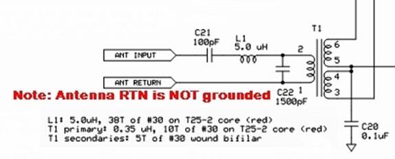
L1 |
5.0 uH |
38T #30 on T25-2 (red) Toroid Core (approx 14” of wire) |
1 |
|
T1 |
Transformer |
Primary: 10T #30 on T25-2 (red) Toroid Core Secondaries(2): 5T of #30 bifilar atop primary winding |
1 |
|
C20 |
0.1 uF |
SMT cap |
1 |
|
C21 |
100pF |
Ceramic Cap (“101”) |
1 |
|
C22 |
1500 pF |
Ceramic Cap (“152”) |
1 |
Schematic
Installation Notes
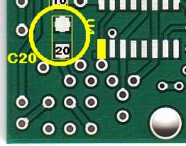
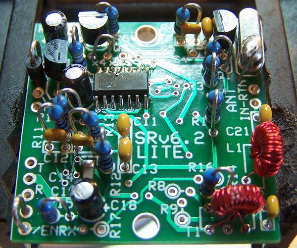
SMT Cap C20 is installed at the bottom side, lower-left:
Topside Components
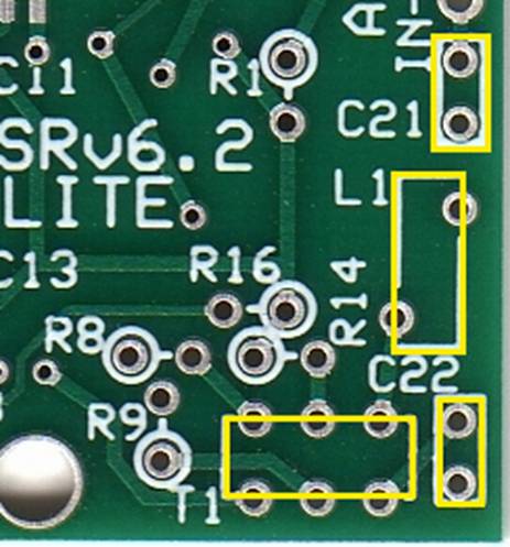
Ceramic Caps
c C21 (100 pF – code = “101”) and
c C22 (1500 pF – code = “152”) are installed as shown in the topside picture, above
Inductors
c
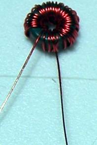
L1: wind
38 turns of #30 wire (requires about 14” of wire) onto a T25-2 (Red) toroid core.
This should produce a 5 uH inductance.
Each pass through the center of the core is counted as a turn when winding
the inductor. L1 is mounted vertically and supported by its
leads.
Be sure to remove the enamel coating on the wire before attempting to solder an
inductor lead to its associated mounting hole.
The enamel coating on the #30 wire provided in the kit does not heat
strip
very well but may be stripped by use of a small folded over piece of Emory paper where the lead is pulled through two facing surfaces of the Emory paper multiple times to sand off the enamel coating on the wire end.
See the tutorial on winding toroids for details on winding a single-winding coil.
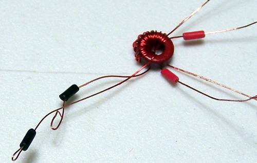
c
T1: This transformer has a single winding
primary and a bifilar winding secondary, wound with #30 wire onto a T25-2 (red)
toroid. The 10 turn primary winding,
using 10” of #30 wire, should yield 0.35
uH. The 5 turn secondary uses two 5”
lengths of #30 wire, twisted together into a bifilar pair that has
approximately 2-3 twists per inch.
Transformer T1 is mounted vertically and raised above the board about 1/8 of an
inch. In winding T1, first wind the
primary winding with 10 turns #30 AWG enameled wire (approximately 10” of wire)
so that the primary winding starts and ends at about the same point on the core
and is uniformly spread around the core.
Twist two 5” pieces of #30 enameled wire together and wind the secondary
windings with the windings starting and ending just slightly clockwise around
the core from where the primary winding starts and ends. After striping and tinning each transformer
lead at about 1/8 of an inch from the
core, determine the two pairs of leads of each of the secondary windings by use
of an ohmmeter.
I like to use short lengths of insulation from hookup wire to identify two of
the 3 sets of leads in these transformers.
The windings and their mounting positions at the lower right-hand position on
the topside are shown below:
Either secondary winding may be designated as the first secondary winding.
c
When the transformer is positioned vertically
with its leads to the appropriate plated through-holes, solder all the leads
and cut leads flush to the bottom side of the board.
See the video
tutorial showing winding and
mounting
a similar transformer for another Softrock kit.
Tests
The inductors are the second most common causes of RX problems in the Softrock kits. Therefore, these tests are critical to the project.
Current Draw
There should be no appreciable change in current draw from the previous stage.
Resistance
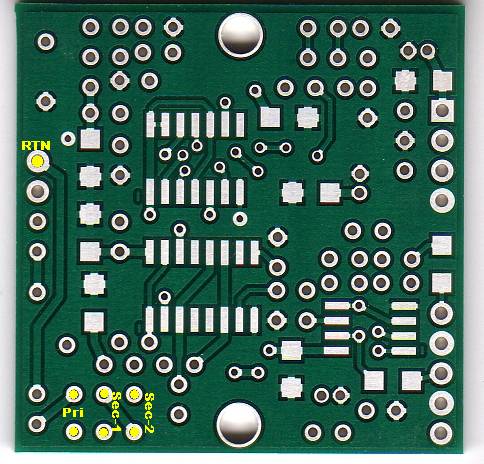
c
Each of the primary plated through-holes should
show about zero ohms resistance to the antenna return hole, (RTN), on the upper
right edge of the board.
Voltages
c Apply power to the board
c
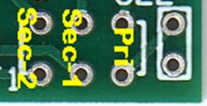
Measure the voltage (WRT Ground) at each of the
secondary terminals of the transformer T1.
Each should measure ~2.5 Vdc.
(author 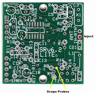 measured 2.48
Vdc)
measured 2.48
Vdc)
c Power off
Scope (board remains unpowered)
c Inject a ~2 volt p-p signal at around 7 MHz into the ANT-IN pad. Once again, you can probably just use a cutoff component lead and poke it through the empty lead hole without soldering.
c Connect the scope probes to the points shown (yellow dots) below and connect the probe ground leads to ground.
c
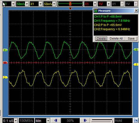
Phasing
Test: Trigger your scope with channel 1. You should have an equal
amplitude, opposite phase signal displayed. If they are in phase, you probably
aren't triggering the scope on channel 1. If either one is missing, double
check the solder connections for T1.
Your test results should resemble the fo9llowing (the key result is the phase
difference of 180 degrees):
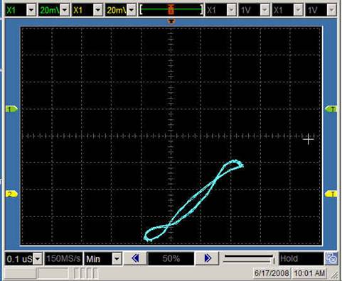
c Lissajous Pattern (X-Y) Test: Change your scope setting to “X-Y” to get a lissajous pattern of the two signals together. If the phasing is perfectly 180 degrees out of phase, we should see a single diagonal line. In reality, there will be some non-zero (but hopefully low, on the order of 5% of the input) signal shown on the scope:
Completed Stage
You have completed one of the more tedious stages in building the kit (at least, for me, the winding of toroids and stripping the enamel without breaking the leads is certainly tedious). If you have passed the tests described here, you are well on your way. The only part left is the Mixer stage, followed by connecting the radio to the outside world and actually using it..
Topside
Bottomside