Home BOM PS LO DIV Op-Amp RF Mixer Connect
II – Softrock Lite V6.2 – Local Oscillator
Parts
|
Designation |
Description |
Type
Component |
Quantity |
|
C3 |
100 pF, 5% (code = “101”) |
ceramic |
1 |
|
C5 |
22 pF, 5% (code=”22J”) |
ceramic |
1 |
|
C1, C2 |
0.1uF, |
smt 1206 |
2 |
|
R1 |
10 ohm |
¼ W 1% |
1 |
|
R2, R3 |
10 K ohm |
¼ W 1% |
2 |
|
R4, R7 |
499 ohm |
¼ W 1% |
2 |
|
R5 |
1K ohm |
¼ W 1% |
1 |
|
C4 |
not used with 40m board |
n/a |
0 |
|
R6 |
22.1K ohm (not used in 40m) |
¼ W 1% |
0 |
|
Q1 |
2N3904 NPN |
TO92 |
1 |
|
Q2 |
2N3906 PNP |
TO92 |
1 |
|
X1 |
28.224 MHz |
HC49 |
1 |
|
misc |
short resistor lead |
For jumper |
1 |
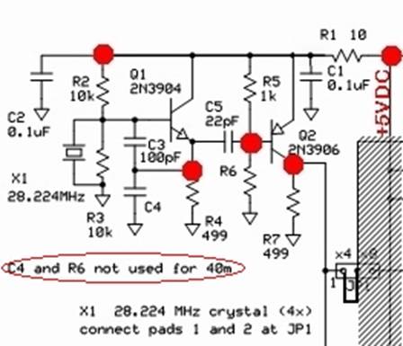
Schematic
Installation Notes
c
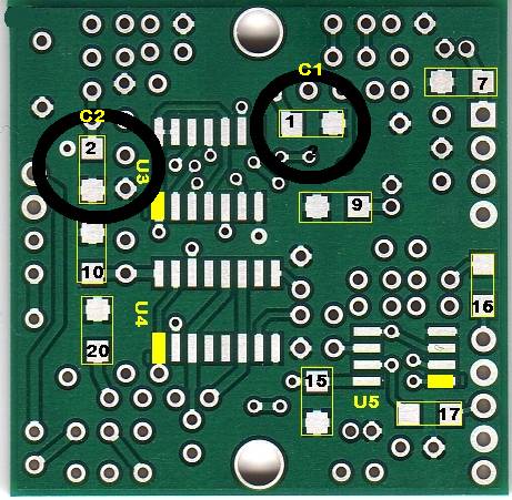
Install the two SMT Caps (C1 and C2) on the bottom
side of the board (refer to the SMT
Chip Soldering Guide)
JP1
c
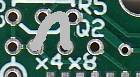 Mount a small wire loop
to bridge the x4 holes, holes 1 and 2, of JP1. (This will result in each
crystal frequency being divided by four in the clocking of the QSD and QSE
circuits. The center frequency resulting from the x4 jumper will be
approximately the crystal frequency divided by four, or 7.056 MHz)
Mount a small wire loop
to bridge the x4 holes, holes 1 and 2, of JP1. (This will result in each
crystal frequency being divided by four in the clocking of the QSD and QSE
circuits. The center frequency resulting from the x4 jumper will be
approximately the crystal frequency divided by four, or 7.056 MHz)
Transistors
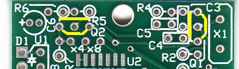
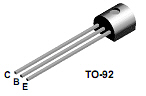
Install the transistors, Q1 and Q2. Use the body shape silk screen marking to help in proper placement of each transistor. Caution: be sure to carefully observe the markings on the transistors and distinguish the 3904 (Q1) from the 3906 (Q2)
c Q1 2N3904 (next to X1)
c
Q2 2N3906
(left of top mounting hole)
Resistors
Install resistors R1 through R5 and R7. R6 is NOT used for the 40m rig. Resistors are typically mounted on the board
in a hairpin fashion with the body of each resistor located over its silkscreen
circle. This is important because the
test points (red dots on the schematics) are at the tops of the hairpins, are
based on the assumption  that this installation
technique was used. Resistors will be
oriented in one of the following orientations:
that this installation
technique was used. Resistors will be
oriented in one of the following orientations:
1. West-East: The body is on the left (west) and the hairpin is on the right (east) – as in the example shown here
2. East-west: The body is on the right (east) and the hairpin is on the left (west)
3. North-south: The body is on the top (north) and the hairpin is on the bottom (south)
4. South-north: The body is on the bottom (south) and the hairpin is on the top (north)
c R1 10 Ohm (hairpin: north-south)
c R2 10k Ohm (hairpin: west-east)
c R3 10k Ohm (hairpin: north-south)
c R4 499 Ohm (hairpin: west-east)
c R5 1k Ohm (hairpin: east-west)
c
R6 (not used in 40m
rig
c R7 499 Ohm (hairpin: south-north)
Ceramic Capacitors
See the Ceramic Capacitor Identification Section for how to decode the markings on the ceramic capacitors.
c C3 (100pF, code=”101”, orientation is vertical)
c
C4 (not used in the
40m rig)
c C5 (22 pF, code=”22J”, orientation is horizontal).
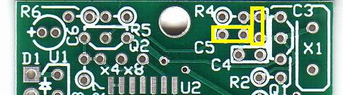
Crystal
c
Mount the HC49 crystal mounting in the upper
right corner of 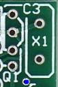 the board, mounting it
vertically to the board. A small
plated-through hole in the lower left corner of the crystal mounting position
(blue hole in illustration at right) provides a place for a grounding wire to
be soldered to the metal crystal case.
The grounding wire also provides additional mechanical support for the
crystal. Make sure the crystal is
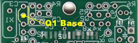
mounted slightly above the board since a trace runs on top of the board
from one of the crystal holes to the base of Q1. You can use a piece of cardboard or wire
insulation between the bottom of the crystal and the board to get the desired
standoff distance while mounting X1.
the board, mounting it
vertically to the board. A small
plated-through hole in the lower left corner of the crystal mounting position
(blue hole in illustration at right) provides a place for a grounding wire to
be soldered to the metal crystal case.
The grounding wire also provides additional mechanical support for the
crystal. Make sure the crystal is
mounted slightly above the board since a trace runs on top of the board
from one of the crystal holes to the base of Q1. You can use a piece of cardboard or wire
insulation between the bottom of the crystal and the board to get the desired
standoff distance while mounting X1.
Tests
Current Draw
c Connect the ammeter in series with the power leads to measure the current draw.
c
Expected current draw will be on the order of 10.8 mA, using a fresh 9V battery as
the power source. Author’s test resulted
in 10.9 mA (using a 9 Vdc battery
with the 5 volt rail measuring 4.92 Vdc.
Voltages (WRT Ground – on 9V battery power)
Note:
When
using a DVM for measuring voltage in an active linear circuit it is always
recommended to add a 100K resistor in series of the
measuring
probe tip. This cancels the probe from capacitive loading the circuit and prevents
possible spurious oscillation that can change the operating point of the
measured circuit. Best make a small connector that you can plug the probe into,
solder a short leaded 100K resistor and put some epoxy on the resistor and
socket to make it strong.
(Thanks to Victor - 4Z4ME for the tip.)
c R1 hairpin should = the 5 vdc rail voltage (between 4.5 and 5.4 vdc – Author’s test measured 4.92 Vdc)
c Collector of Q1/Emitter of Q2 (R2 hairpin) should be around 4.86 Vdc (Author: 4.87 Vdc)
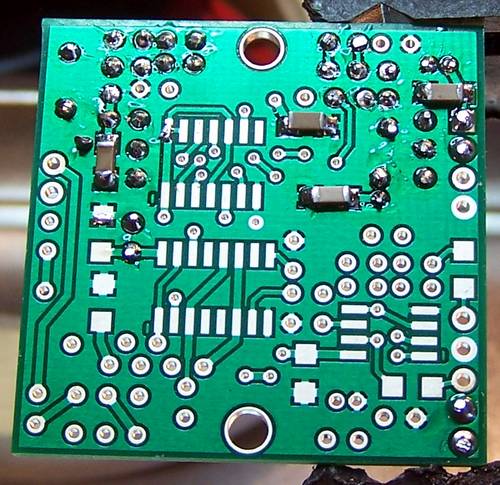
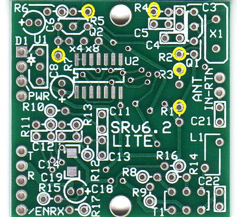
c Base of Q1 (see bottomside view, above) should be about 48% of the voltage measured at the R2 hairpin (Author measured 2.34 Vdc)
c Emitter of Q1 (R4 hairpin) should be around 0.7 V below the base voltage, or 1.66 Vdc (Author: 1.65 Vdc)
c Base of Q2 (R5 hairpin) should be around 4.87 Vdc (Author: 4.87 Vdc)
c Collector of Q2 (measure at the jumper lead of JP1) should be around 3.22 Vdc (Author: 3.21 Vdc)
Frequency
The frequency of the LO’s output should be 4 times the desired center frequency 7.056 MHz, or 28.224 MHz. Check this if you have a good frequency counter and/or scope, or a receiver you can tune into 28.224 MHz.
Note: if your kit is the 20m kit, this is a little different. The Upgraded 20m SoftRock Lite kit uses 1/3 sub-harmonic sampling to give 20m receive function. The center frequency is approximately 3 * 18.73 / 4 = 14.047 MHz. The loss in sensitivity associated with the 1/3 sub-harmonic sampling, about 3 or 4 dB, is made up by 5x gain, (compared to the 40m SoftRock Lite), in the I / Q audio stage where a low-noise LT6231 op-amp is used in lieu of the TVL2462CD opamps.
.
Waveform
c The LO output on a scope should resemble a sine wave of 28.224 MHz frequency (author measured 27.78 MHz – close enough, given the limited quality of the author’s scope)
c The p-p voltage should be approximately 4.2 volts p-p (Author: 4.34 V p-p – close enough)
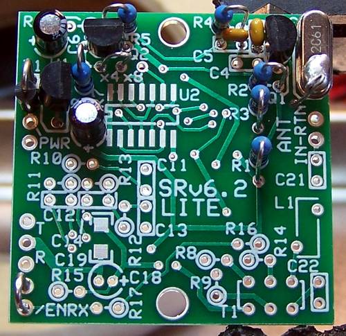
Completed Stage
You now have a local oscillator putting out a nice strong signal that is 4 times the desired center frequency. The next stage is the place where we:
- Divide the LO’s output down into two signals that are 7.056 MHz, our desired center frequency
- Shift the phase of one of those two signals to 90 degrees away from the other.
There are two challenges in the Dividers Stage coming up. One is handling and soldering SMT ICs. You should review the materials, tutorials, and references provided in the home page if you feel you need brushing up on SMT soldering.
The other challenge is the close quarters within which you will have to work to install one of the Divider chips (U2 - the one on the topside).
Topside
Bottomside