Home BOM PS LO DIV Op-Amp RF Mixer Connect
VII – External Connections
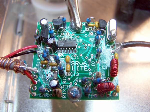
To connect the Softrock Lite V6.2 to the outside world, you will need to provide three connections. The first, and most obvious, is the power connection of your choice; the second, is the antenna connection; and the third is the I and Q output connection.
Power Connection
Connect DC power leads to the pair of plated through-holes just below D1 on the left edge of the board. The plated through-hole nearest to D1 is the positive connection to a DC power source and the lower of the two plated through-holes is the power supply negative connection or circuit ground.
Antenna Connection
Connect a length of 50 ohm coax to the antenna connection on the right edge of the board near the upper right corner. The upper of the two plated through-holes is the antenna return connection to the coax shield and the lower plated through-hole is the coax center conductor connection.
I and Q (soundcard) Connection
A stereo audio cable may be connected at this time to the board at the three plated through-holes along the lower left edge of the board near the lower left corner. Use a short piece of #22 bus wire to connect the middle plated through-hole (ground) to the shield (barrel) of the cable and wrap the end of the bus wire around the outside of the cable several turns for strain relief of the cable. The tip of the stereo cable plug connects to the plated through-hole that is marked with the letter T on the board and the ring of the stereo cable plug connects to the plated through-hole marked with the letter R.
Final Test
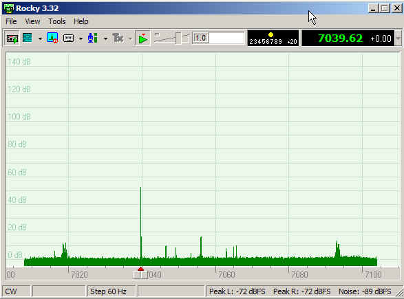
After installing the hookup connections, the author conducted a final test using the Norcal S9 Signal Generator to generate a 50 uV, 7.040 MHz signal into the antenna lead. The audio I and Q outputs were connected into an SB Live 24 bit USB sound card on a computer running Rocky 3.2 with the center frequency set to 7.056 MHz. The results are as shown in the graphic below.