Introduction
Theory of Operation
The Dividers stage takes in the local oscillator's signal and divides it by 4, producing two output signals. Each output signal is at a frequency that is ¼ the stage's input signal and is a square wave with 50% duty cycle. The 50% duty cycle is with respect to the4 5V rail.The signals are "in quadrature", that is, they are 90° out of phase with each other. These are provided to the TX and RX mixer stages as clocking signals. They are called out on testpoints marked "QSD", for the I and Q signals to mix down the incoming "chunk" of RF, and "QSE", for the I and Q signals which mix up the PC's line out signals.
Schematic
Summary Build Notes
- Install U9
- Install Resistors R44-45
- Test the stage
Bill of Materials
| Check | Designation | Component | (Color) Code | Type | Qty | Notes |
|---|---|---|---|---|---|---|
| [__] | R44 | 10 k | brown-black-black-red-brown | Resistor 1% | 1 | FlatH |
| [__] | R45 | 10 k | brown-black-black-red-brown | Resistor 1% | 1 | FlatH |
| [__] | U9 | 74AC74 | SOIC-14 SMT Dual FF | 1 | (bottom) |
Detailed Build Notes
This stage mainly adds the frequency division and phase-shifting capabilities via the AC74 dual flip flop. The builder must take necessary ESD precautions. See the guidelines on installing SMT ICs.Bottomside Components
Install The AC74 SMT IC, U9
See the guide for installing SMT ICs.Note, also, that
ESD Precautions are in order here.
- Install IC U9.
- See table below for orientation
| Check | Designation | Component | Orientation |
|---|---|---|---|
| U9 | 74AC74 | 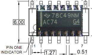
|
Topside Components

Install the 2 Resistors
- Install the two resistors (R44 and R45) that provide the voltage divider for the IC.
- R44 and R45 are installed flat style and horizontal
Completed Board
Topside
Bottomside
Testing
Current Limited Power Test
- Connect a 100 ohm resistor in series with the power line and apply 12 V dc power
- the current should be less than 120 mA (nominally around 80 mA)
- Measure the voltage WRT ground at the +5 V and at the 3.3 Vdc testpoints.
- A voltage of around 2 V dc indicates the power rails are not shorted
Current Draw(DMM)
- Current numbers here are for the CMOS version of the Si570. You will need to adjust these upward by anywhere from 12 to 15 mA for the LVDS version.
- Then set SW1 to "0100", apply power, and measure the current with your DVM's mA meter.
- The current draw should be < 88 mA (or about 4 - 6 mA greater than the preceding stage's current draw). Author measured 79.6 mA.
- Remove the current-limiting resistor. Subsequent tests in this stage are with the current-limiting resistor OUT of the circuit.
Voltage Tests (DMM - 2.5 Vdc)
To determine if the dividers are clocking correctly, we need to check the pin voltages on U9. Unexpected values here usually point to problems with soldering U9 and/or the voltage dividing resistors R44 and R45.If these tests are successful, you can be fairly certain that the dividers are clocking correctly.
- Using a DMM, measure the output of the voltage divider with respect to ground. Measure at the left-hand lead of either R44 or R45. This should yield approximately ½ the 5 volt rail voltage.
- Measure the voltages (with respect to ground) on the pins of U9. It is best to test for these voltages at the actual pins (not the pads), thereby ensuring correct soldering of the pins to the pads.
| Test Point | Units | Nominal | As Actually Measured (Power ON) |
|---|---|---|---|
| (topside) left-hand lead of R44 or R45 | Vdc | 2.5 (½ the 5 volt rail) | |
| U9, Pins 1, 4, 10, 13, 14 | Vdc | 5 | |
| U9, Pins 2, 3, 5, 6, 8, 9, 11, 12 | Vdc | 2.5 (½ the 5 volt rail) | |
| U9, Pin 7 | Vdc | 0 |
U9 Center Frequency Output Test
You can validate the dividers' frequency output by tuning your HF receiver to one of the center frequencies (see SW Settings) and loosely coupling the receiver's antenna via a tickler wire laid over the board. You should hear the output as quieting in the receiver.(Optional Test) U9 Output
While not necessary, you may also check the dividers' output using a scope. U9 sends I and Q signals to the mixer's S0 and S1 inputs. These signals are available at the 2 QSD testpoints (as well as at the 2 QSE testpoints) near the bottom edge of the board's topside (see above).
Do not attempt these scope tests unless you have a good quality, calibrated scope with correctly compensated probes. Lesser quality scopes (such as the one shown below!) are good for little more than indicating the presence or absence of a signal, something you can do with an external ham radio RX.
- Use a dual channel oscilloscoipe, triggering on Channel 1, and
- measure the S0 and S1 outputs at the QSD (or, if you wish, QSE) testpoints on the top side of the board, as indicated above.
- They should both be the same frequency (¼ of the LO Output) - assuming you use the SW 1 settings from the LO test, that would be 7.046 mHz) and should be in quadrature (90° out of phase with each other). The image below shows approximations of p-p voltages and frequencies of the 2 quadrature signals.
- They should be approximately 5V p-p square waves. The square waves may have a fair amount of ringing on them depending on your scope quality and connection to the circuit board (see Waveforms below).
Divider Output Waveforms on El Cheapo Scope (Quadrature, 7.046 MHz)