Resistors
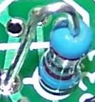
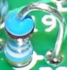
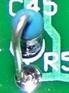
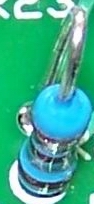
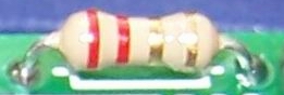
The resistors are mounted with one of five orientations. The first four are the "hairpin" style, where the body of the resistor is snugged up against the board at the location indicated by the silkscreened circle and the other lead is bent into a hairpin shape and inserted into the hole pointed to by the small line on the resistor's silkscreened circle. Hairpin resistor orientations are described in "to-from" terms, indicating the direction the hairpin is pointing in relation to the resistor's silkscreened circle. For example, "east west" means the resistor is mounted hairpin style with the hirpin lead to the west (left) of the body.
The fifth resistor orientation is "flat".
The pictures below illustrate these mounting techniques:
| Orientation | Silkscreen | As Mounted |
|---|---|---|
| East-West |

|
|
| West-East |

|
|
| North-South |

|
|
| South-North |

|
|
| Flat |

|
|
Ceramic Capacitors
ValuesCeramic capacitor value codes are typically expressed as three digits where the first two digits are the significant figures of the capacitor value and the third digit indicates how many zeros to add to express the capacitor value in pF. Examples would be:
- code 471 would indicate a 470 pF capacitor code 2
- 20 would indicate a 22 pF capacitor.

| 1st Digit | 2nd Digit | Multiplier Code | Multiplier | Tokerance Code | Tolerance |
|---|---|---|---|---|---|
|
0 |
0 |
0 |
1 |
B |
± 0.1pF |
|
1 |
1 |
1 |
10 |
C |
± 0.25pF |
|
2 |
2 |
2 |
100 |
D |
± 0.5pF |
|
3 |
3 |
3 |
1,000 |
F |
± 1% |
|
4 |
4 |
4 |
10,000 |
G |
± 2% |
|
5 |
5 |
5 |
100,000 |
H |
± 3% |
|
6 |
6 |
|
|
J |
± 5% |
|
7 |
7 |
|
|
K |
± 10% |
|
8 |
8 |
8 |
0.01 |
M |
± 20% |
|
9 |
9 |
9 |
0.1 |
Z |
+80% / -20% |
- Lightly snug each capacitor as close to the board as the lead formation will allow.
- Slightly spread the capacitor leads on the bottom side of the board and solder one lead to hold the capacitor in position.
- Cut both leads flush to the bottom of the board and solder the second capacitor lead.
| Designation | Component | Type | Qty | Notes | Circuit |
|---|---|---|---|---|---|
| C01 | 4.7 µF | ceramic | 1 | PS-1 | |
| C03 | 4.7 µF | ceramic | 1 | PS-1 | |
| C07 | 4.7 µF | ceramic | 1 | PS-2 | |
| C10 | 0.01 µF | ceramic | 1 | LO | |
| C100-1 | 390 pF | ceramic | 1 | BPF-160 | BPF-1 |
| C100-2 | 560 pF | ceramic | 1 | BPF-80/40 | BPF-2 |
| C100-3 | 180 pF | ceramic | 1 | BPF-30/20/17 | BPF-3 |
| C100-4 | 82 pF | ceramic | 1 | BPF-15/12/10 | BPF-4 |
| C101-1 | 5600 pF | ceramic | 1 | BPF-160 | BPF-1 |
| C101-2 | 600 pF | ceramic | 1 | BPF-80/40 | BPF-2 |
| C101-3 | 220 pF | ceramic | 1 | BPF-30/20/17 | BPF-3 |
| C101-4 | 330 pF | ceramic | 1 | BPF-15/12/10 | BPF-4 |
| C14 | 4.7 µF | ceramic | 1 | OpAmp | |
| C17 | 0.047 µF | ceramic | 1 | OpAmp | |
| C18 | 0.047 µF | ceramic | 1 | OpAmp | |
| C19 | 220 pF | ceramic | 1 | OPAMP | |
| C20 | 220 pF | ceramic | 1 | OPAMP |
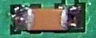
SMT Capacitors
Caveat: Note that the SMT caps are of two types: there are 5 SMT caps that are 0.1 µF; there are 10 SMT caps that are 0.01 µF. Do not get them mixed up.
All SMT capacitor locations on the bottom of the board are to be filled with 1206 size capacitors. You want to do your work on a cookie sheet or other "pan" with sides so, if you accidentally sneeze or otherwise "launch" one of these tiny chips, you may still have a chance of retrieving it.
Installation procedure is as follows for each SMT 1206 Capacitor
- Add a little solder to one pad and tack one end of a capacitor to a pad.
- Reheat and position the capacitor with the tip of the soldering iron and a toothpick.
- When the capacitor is properly positioned on its pads, solder the other end with enough solder to make a small fillet between the end of the capacitor and the pad.
- < Reheat the first end of the capacitor and add a little solder, if necessary, to make a small fillet at the tacked down end of the capacitor.
-
Leonard KC0WOX has an excellent video on installing SMT Caps.
SMT ICs
Installation procedure is as follows for each Surface Mount Technology (SMT) IC:
- Orient the IC on its pads so that the pin 1 corner of the IC matches the small 1 (it also looks like a 0) mark in the copper on the bottom side of the board. In general, pin 1 of an SOIC packaged IC is in the lower left corner of the package when the printing on the package top reads upright, from left to right.
- Tack-solder one corner pin of an IC and reheat the tacked pin as necessary to line up the IC on its pads properly.
- Check the orientation of the IC and the line up of the IC on its pads with magnification and good lighting.
- If all is well, carefully solder the rest of the leads to their pads.
- Carefully and closely inspect the pins to look for bridges caused by excessive solder or debris on or around the pads.
- Use solder wick to remove any excess solder or solder bridges between IC pins.
- Using high (3x or better) magnification, carefully check each pad and solder joint.
Leonard KC0WOX has an excellent video on installing surface mount ICs. The Sparkfun website also has some good video materials on soldering and wicking SMT ICs.
SMT IC Components (samples from Lite+Xtall V8.3 RX)
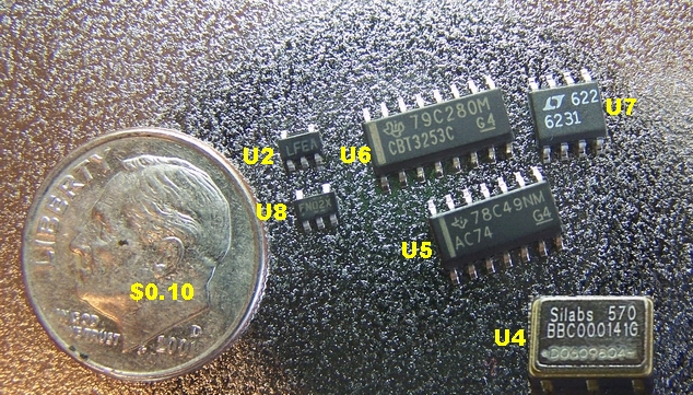
The Surface Mount ICs in the "XTALL + Lite" RX V8.3 kit are listed below:
| V8.3 Designation | Component | Type | Qty | Notes | Circuit |
|---|---|---|---|---|---|
| U2 | LP2992AIMS-3.3V | 3.3v Regulator% | 1 | (bottom) "LFEA" | PS-2 |
| U4 | Si570 LVDS | Oscillator | 1 | (bottom)not from Tony | LO |
| U5 | 74AC74 | SOIC-14 SMT Dual FF | 1 | (bottom) "AC74" | DIV |
| U6 | FST3253MX | SOIC-14 SMT Mixer | 1 | (bottom) "FST3253MX" | Mixer |
| U7 | LT6231 | SOIC-8 OpAmp | 1 | (bottom) "6231" | OpAmp |
| U8 | FIN1002 | Diff LVDS Rcvr | 1 | (bottom) "FN02X" | LO |