Introduction
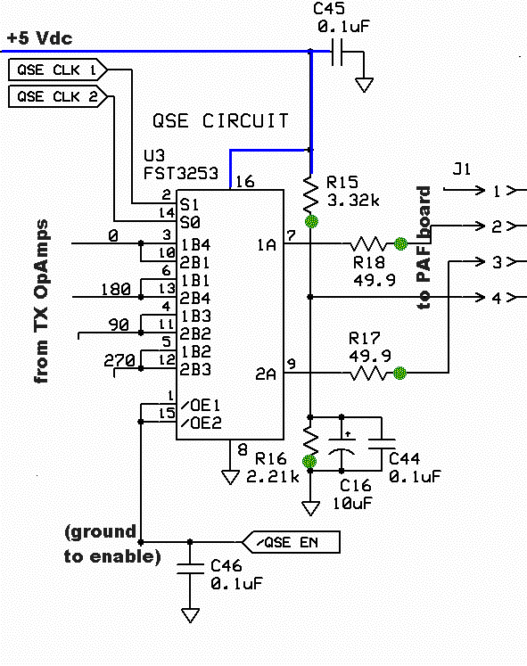
This stage adds the TX Mixer to the board and provides the modulation of the Dividers' output signals by the 4 I and Q signals from the OpAmps. The result is a double sideband RF waveform that will be coupled into the PA stage.
Schematic
Summary Build Notes
- Install sockets J1 and J2
- Install Resistors R15-R16
- Install electrolytic Cap C16
- Install U3
- Test the Stage
Bill of Materials
| Check | Designation | Component | (Color) Code | Type | Qty | Notes |
|---|---|---|---|---|---|---|
| [__] | C16 | 10 uF 16V | electrolytic | 1 | S=+ | |
| [__] | J1 | 4-pin socket | connector (female) | 1 | ||
| [__] | J2 | 5-pin socket | connector (female) | 1 | ||
| [__] | R15 | 3.32 k | orange-orange-red-brown-brown | Resistor 1% | 1 | FlatV |
| [__] | R16 | 2.21 k | red-red-brown-brown-brown | Resistor 1% | 1 | FlatV |
| [__] | R17 | 49.9 | yellow-white-white-gold-brown | Resistor 1% | 1 | FlatV |
| [__] | R18 | 49.9 | yellow-white-white-gold-brown | Resistor 1% | 1 | FlatV |
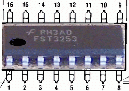
| [__] | U3 | FST3253 | SOIC-16 Dual 4:1 Mux/Demux Bus Switch | 1 | (bottom) |
Detailed Build Notes

Sockets
- From the PAF kit, take the PAF board and plugs P201 and P202
- Install the plugs to the bottom side of the PAF board with the short leads of each plug inserted into the holes and protruding from the bottom to the top and the long leads protuding from the bottom of the PAF board.
- Using the PAF board and its plugs as an alignment jig, plug it into the sockets J1 and J2
- Mount and install the sockets J1 and J2 onto the topside of the Main Board
- Remove the PAF board and set aside until later
Resistors and Capacitor
- Install Resistors R15-R18
Note they are all oriented flat, vertical. - Install electrolytic capacitor C16
Mixer SMT IC
Install The FST 3253 TX Mixer, U3Usual ESD and solder splashover precautions apply.
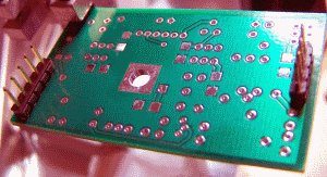
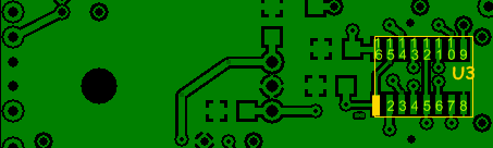
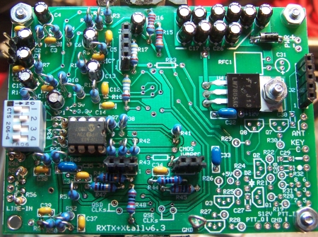
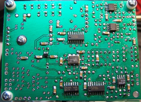
Completed Board
Topside
Bottomside
Testing
Current Limited Power Test
- Connect a 100 ohm resistor in series with the power line and apply 12 V dc power
- the current should be less than 120 mA (nominally 105 mA)
- Measure the voltage WRT ground at the +5 V and at the 3.3 Vdc testpoints.
- A voltage of around 2 V dc indicates the power rails are not shorted
- Remove the current-limiting resistor. Subsequent tests in this stage are with the current-limiting resistor OUT of the circuit.
Current Draw
- Without limiting resistor, you should get < 103 mA
- Your measurement: _____________________________
Mixer Pin Voltages
- Set PTT-I to high by jumpering the PTT-I pad to the left-hand lead of D1
- Jumper pins 2, 3, and 4 of jack J1 (this establishes the correct dc level for pins 7 and 9 of the mixer)
- Measure the voltages at the mixer pins as indicated below:
| Pin | Nominal Value | Author Results | Your Measurement |
|---|---|---|---|
| 1&15 (hole for R26 hairpin) | ~0 - .050 Vdc | ||
| 8 | 0 | ||
| 16 | 5 V rail | ||
| 2 & 14 (QSE CLK 1 & 2) | ½ 5V rail | ||
| 7(R18 hairpin) | around 2 volts | ||
| 9 (R17 hairpin) | around 2 volts | ||
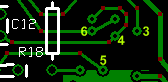
| 3 (see picture above right) | around 2 volts | ||
| 4 (see picture above right) | around 2 volts | ||
| 5 (see picture above right) | around 2 volts | ||
| 6 (see picture above right) | around 2 volts |