Introduction
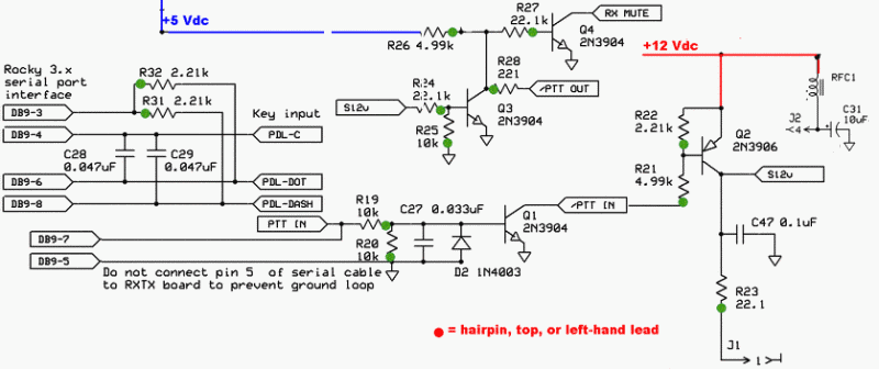
This and the next stage wrap up some miscellaneous enabling functionality to handle switching between RX and TX.
The circuitry for connecting the PTT and Keyer inputs up to Rocky via a serial interface is installed in this stage (minus the DB9 connector, which will be installed in the "External Connections" stage.
The PTT (PTT_I tab on the board) can be activated with +12V from the RS232C signal of the Rocky Interface, OR with +5V from other sources (e.g. a +5V uC signal). If you are using Rocky, you may not need to connect the GND as the GND return may flow through the audio connectors already.
Also available from Tony Parks is a USB I2C interface. That interface's PTT_OUT (Rx = 0V, Tx = 5V) can be connected to the SRv6.x's PTT_IN.
Schematic
Summary Build Notes
- Install Ceramic Caps C27-C29
- Install Elactrolytic cap C31
- Install Resistors R19-R28, R31-R32
- Install D2, Q1-Q4
- Wind and install RFC1
- Test the Stage
Bill of Materials
| Check | Designation | Component | (Color) Code | Type | Qty | Notes |
|---|---|---|---|---|---|---|
| [__] | C27 | 0.033 uF | 333 | ceramic | 1 | |
| [__] | C28 | 0.047 uF | 473 | ceramic | 1 | |
| [__] | C29 | 0.047 uF | 473 | ceramic | 1 | |
| [__] | C31 | 10 uF 16V | electrolytic | 1 | S=+ | |
| [__] | RFC1 | 23 uH | choke 4T #26 | 1 | BN-43-2402 5" | |
| [__] | R19 | 10 k | brown-black-black-red-brown | Resistor 1% | 1 | E-W |
| [__] | R20 | 10 k | brown-black-black-red-brown | Resistor 1% | 1 | W-E |
| [__] | R21 | 4.99 k | yellow-white-white-brown-brown | Resistor 1% | 1 | N-S |
| [__] | R22 | 2.21 k | red-red-brown-brown-brown | Resistor 1% | 1 | N-S |
| [__] | R23 | 22.1 | red-red-brown-gold-brown | Resistor 1% | 1 | FlatH |
| [__] | R24 | 22.1 k | red-red-brown-red-brown | Resistor 1% | 1 | N-S |
| [__] | R25 | 10 k | brown-black-black-red-brown | Resistor 1% | 1 | N-S |
| [__] | R26 | 4.99 k | yellow-white-white-brown-brown | Resistor 1% | 1 | N-S |
| [__] | R27 | 22.1 k | red-red-brown-red-brown | Resistor 1% | 1 | E-W |
| [__] | R28 | 221 | red-red-brown-black-brown | Resistor 1% | 1 | E-W |
| [__] | R31 | 2.21 k | red-red-brown-brown-brown | Resistor 1% | 1 | W-E |
| [__] | R32 | 2.21 k | red-red-brown-brown-brown | Resistor 1% | 1 | W-E |
| [__] | D2 | 1N4003 | Diode | 1 | ||
| [__] | Q1 | 2N3904 | Transistor (NPN) TO-92 | 1 | ||
| [__] | Q2 | 2N3906 | Transistor (PNP) TO-92 | 1 | ||
| [__] | Q3 | 2N3904 | Transistor (NPN) TO-92 | 1 | ||
| [__] | Q4 | 2N3904 | Transistor (NPN) TO-92 | 1 |
Detailed Build Notes
Install the Capacitors and Resistors
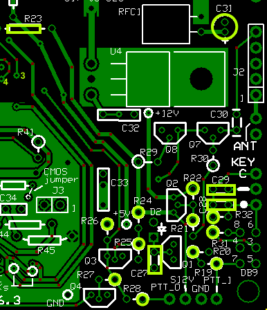
| Check | Designation | Component | (Color) Code | Type | Qty | Notes |
|---|---|---|---|---|---|---|
| [__] | C27 | 0.033 uF | 333 | ceramic | 1 | |
| [__] | C28 | 0.047 uF | 473 | ceramic | 1 | |
| [__] | C29 | 0.047 uF | 473 | ceramic | 1 | |
| [__] | C31 | 10 uF 16V | electrolytic | 1 | S=+ | |
| [__] | R23 | 22.1 | red-red-brown-gold-brown | Resistor 1% | 1 | FlatH |
| [__] | R28 | 221 | red-red-brown-black-brown | Resistor 1% | 1 | E-W |
| [__] | R22 | 2.21 k | red-red-brown-brown-brown | Resistor 1% | 1 | N-S |
| [__] | R31 | 2.21 k | red-red-brown-brown-brown | Resistor 1% | 1 | W-E |
| [__] | R32 | 2.21 k | red-red-brown-brown-brown | Resistor 1% | 1 | W-E |
| [__] | R21 | 4.99 k | yellow-white-white-brown-brown | Resistor 1% | 1 | N-S |
| [__] | R26 | 4.99 k | yellow-white-white-brown-brown | Resistor 1% | 1 | N-S |
| [__] | R19 | 10 k | brown-black-black-red-brown | Resistor 1% | 1 | E-W |
| [__] | R20 | 10 k | brown-black-black-red-brown | Resistor 1% | 1 | W-E |
| [__] | R25 | 10 k | brown-black-black-red-brown | Resistor 1% | 1 | N-S |
| [__] | R24 | 22.1 k | red-red-brown-red-brown | Resistor 1% | 1 | N-S |
| [__] | R27 | 22.1 k | red-red-brown-red-brown | Resistor 1% | 1 | E-W |
Install Semiconductors
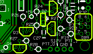
- When mounting D2, mount it hairpin style so the lead going to the square pad is the cathode
(the end with the line)

- Be sure to distinguish between the 2N3904 and the 2N3906 (the markings look very similar).
| Check | Designation | Component | (Color) Code | Type | Qty | Notes |
|---|---|---|---|---|---|---|
| [__] | D2 | 1N4003 | Diode | 1 | N-S | |
| [__] | Q1 | 2N3904 | Transistor (NPN) TO-92 | 1 | ||
| [__] | Q2 | 2N3906 | Transistor (PNP) TO-92 | 1 | ||
| [__] | Q3 | 2N3904 | Transistor (NPN) TO-92 | 1 | ||
| [__] | Q4 | 2N3904 | Transistor (NPN) TO-92 | 1 |
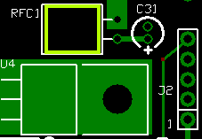
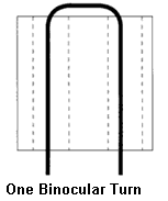
Wind and Install the RFC Choke
- RFC1 needs 4 turns (5") of #26 wire.
- Before winding, take a small drill bit and twirl it in the core holes to smooth/remove any burrs that might otherwise short the coil.
- Remember, when winding a binocular core like the BN-43-2402, each pass where the wire ends up at the same side where it started the pass counts as a turn.
- Use fine grit emery cloth to remove the enamel from the magnet wire up to within 1/8 inch of the core
- Mount the choke so that it lays horizontally flat in the designated space.
| Check | Designation | Component | (Color) Code | Type | Qty | Notes |
|---|---|---|---|---|---|---|
| [__] | RFC1 | 23 uH | choke 4T #26 | 1 | BN-43-2402 5" |
WC5MC TX LED Modification
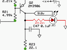
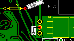
Charles, WC5MC has a nifty little mod (see his documentation) which adds an LED indicator that lights up when power is applied to the PA/Filter (i.e., the rig's PTT-I goes high and enables the TX mode). It involved dead-bugging a 20 k resistor and an LED between the S12V line and circuit ground.
Completed Board
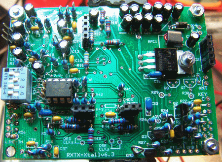
Testing
Current Limited Power Test
- Connect a 100 ohm resistor in series with the power line and apply 12 V dc power
- the current should be less than 120 mA
- Measure the voltage WRT ground at the +5 V and at the 3.3 Vdc testpoints.
- A voltage of around 2 V dc indicates the power rails are not shorted
- Remove the current-limiting resistor. Subsequent tests in this stage are with the current-limiting resistor OUT of the circuit.
Current Draw
- Without current limiting resistor you should see < 103 mA
- Your Measurement: _______________________________

Switching
- Before powering up, attach a clip lead between the left-hand (cathode) lead of
D1 and the "PTT-I"
(this sets PTT_IN = 12 Vdc, ON)
Be careful. Do not apply 12Vdc to the terminal marked "PTT-O" - it causes chips to fry!
- Apply power
- Measure the voltage at the S12V pad. You should get a high signal (e.g., 10-12 Vdc). Your measurement: _________________________
- Measure the voltage at R21 hairpin (/PTT-I). This should get a
low signal, ~0 Vdc.
Your Measurement: _____________________ - Unclip the lead at the D1 cathode (this sets PTT OFF)
- Measure the voltage at the S12V pad again. You should get a
low signal, ~0 Vdc.
Your Measurement: _____________________ - Measure the voltage at R21 hairpin (/PTT-I). This should get a
high signal, well above 0 Vdc (e.g., 10-12 Vdc).
Your Measurement: _____________________
RFC1 Continuity Test
- Apply power to the board
- Measure the voltage wrt ground at Pin 4 of J2 (this is the lower end of the RF Choke
- You should get the value that is on the 12 Vdc rail (author's rail = ~11.07 Vdc).
Your Measurement: _____________________ - If you do not get the expected value, this may be an indication that the RFC's leads were not properly soldered.