The Power Supply
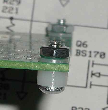 |
The first step is to install the corner hardware. The nuts go on the top side of the board. The hardware will provide "feet" for the board and keep the components that are soldered on the bottom of the board up off of the table surface while working on the top of the board. |
Next, sort out the following parts.
The resistor color bands are extremely hard to read. I would highly recommend measuring each value to insure you install the correct ones! They also roll easily. Be sure to have them loose only in a confined space.
|
1
|
D1 | 1N4003 | Transistor bag | |
|
1
|
R44 | 49.9 ohms | Resistor bag | |
|
11
|
C25-C35 | 10ufd | Capacitor bag | |
|
3
|
C63,C64,C65, | 0.1ufd | Capacitor bag | |
|
1
|
U4 | LM78L05 |
U4 is a 3 terminal voltage regulator converting the +12 volts to 5 volts needed by the integrated circuits. Install C25-C35 observing polarity. The long lead is the + lead. If you install one backwards, when you apply the +12, maximum current will flow, a horrible smell will waft off of the board, and a capacitor may explode or simply bubble liquid. I know this only because that's what they tell me. I would never have experienced this in the past.
R44 body goes next to the board at the bottom pad and the top wire of the resistor is bent gracefully over and goes into the top pad. If you mount Diode D1's anode end down on the right pad, the loop from the top to the left pad can be used to measure the voltage across C25-C34.
We need to install 3 chip capacitors, C63, C64, C65, on the bottom of the board for the power supply. The easiest way to do it is with a small tipped soldering iron, add a little solder to one of the pads. Using tweezers, position and hold the chip cap in position with one end on the solder drop you just added. Heat the solder and the cap will drop down onto the pad. At this time, solder the other end of the cap and then come back and complete the soldering of the first pad. If you haven't done any surface mount soldering, check out the videos, Assembling a digital dial and Assembling a QBSA These were both surface mount projects and the videos show how to solder caps, resistors, transistors, and IC's.
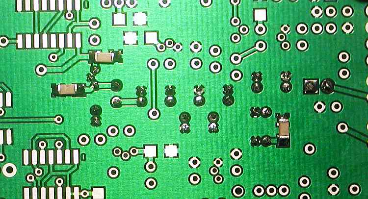
This is what it should look like after soldering all components and adding the chip caps on the bottom.
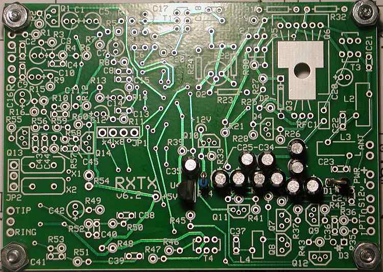
Here's the top.
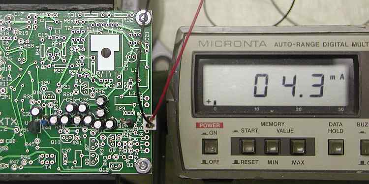
It's now test time. We want to hook 12 volts to the power + and - pins shown just above. Before you power it up though, connect a ma meter in series with the power lead and to be safe, put a 1k ohm resistor in series with the power lead. This can be in either the + or - line. This will limit the current flow if you have a short on the board. After you see that the current isn't excessive, remove it. When you apply power, you should read somewhere around the 4.3 ma shown. If is a lot higher, you probably have a electrolytic capacitor in backwards.
Next, check the voltage as shown. Remember to change your meter out of the current function.
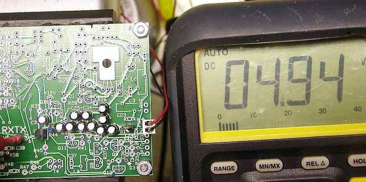
Ok! Now your power supply is working. The next step, the oscillator.
Section 2 - The oscillator section
Section 3 - The divider section
Section 4 - T4 transformer build and test
Section 5 - Installing and testing the op amps
Section 6 - Installing and testing the mixer
Section 7 - Installing and testing the transmitter op amps
Section 8 - Installing and testing the transmitter mixer