Transmitter Mixer
After we install the transmitter mixer, we should start to see RF.
We will need the following parts:
| R17 | 3.32k | resistor bag | |
| R18 | 2.21k |
resistor bag | |
| R19, R20 | 49.9 ohms |
resistor bag | |
| C17 | 10 ufd |
capacitor bag | |
| C18 | 220 pfd |
capacitor bag | |
| C53 | 0.1 ufd |
capacitor bag | |
| U3 | FST3253 |
IC bag | |
| T1 | T30-2 core |

Install the top components.
Install C53 and U3
Wind T1 as per the build instructions, I ended up using 33 turns on the secondary to make it turn out with a measured value of 5.0 uh. I wound the primaries using some red/green wire I had so you can see the proper connections when plugging it into the board.
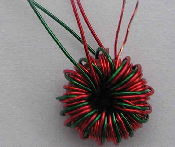
It ended up looking like this. The secondary pair is on the right and the 2 primaries are the red and green wires. Here they are paired up properly for insertion into the board. The slack in the 2 green loops will be pulled out when being soldered.
Here's what it looks like inserted into the board. The red and green wire is heat strippable so they are about ready for soldering.
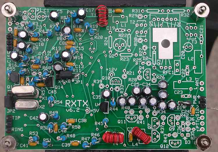
The top should now look like this.
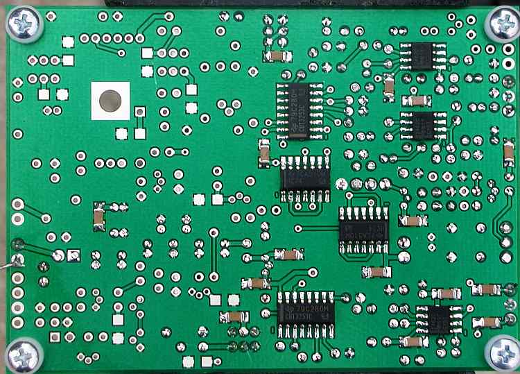
Bottom like this.
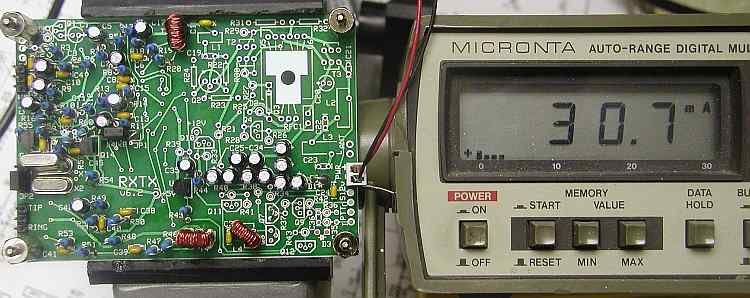
Mine is pulling 30.7 ma's.
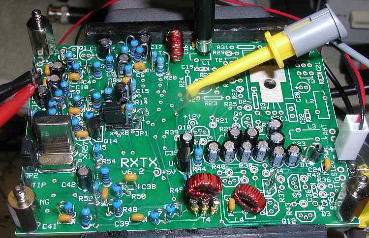
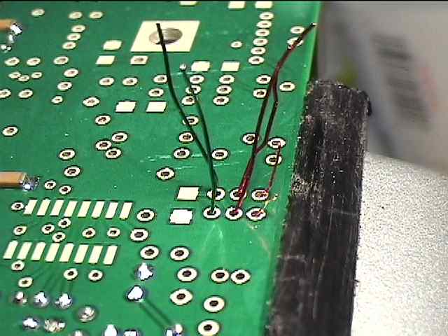
Connect a ground where the yellow test lead is. I know, the picture isn't the greatest but if you locate R39, come off of the hairpin side to the right. Be careful as the point that is circled is +5 volts and you don't want to ground it. The ground is enabling U3. Mine worked without it but it's dangerous to assume voltages are there unless you make the connections yourself. Connect 1 volt of audio, I used 10khz to either the tip or ring of the Line Out connector. Connect the scope to the top right pad of L1. You can use other values but you won't get the same voltage out as I did.
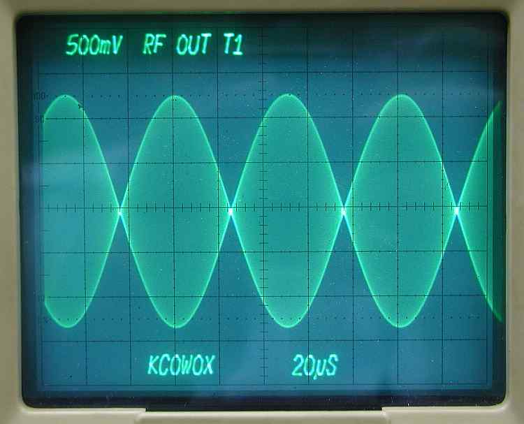
This is a nice , clean. double sideband signal. Actually, very good. On the spectrum analyzer the carrier is suppressed about -55db, We are getting DSB because we don't have a quadrature input from the sound card. That's ok though. The mixer is working properly. If you jumper the same input to the other Line Out input, you should see the voltage increase. On the spectrum analyzer, it increases 3db, which makes sense as you are adding twice the input to the mixer.
Here's a link to a 10 second video of what it looks like on a spectrum analyzer.
What you see initially is the upper and lower sidebands with 20 KHz modulation and then switching to 10 KHz modulation. The carrier is the tiny spike in the middle of the screen. Each vertical division is 10 db.
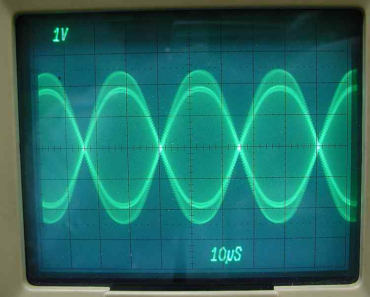
The 7 MHz output doesn't look as clean so if you have this, don't worry about it.
Section 2 - The oscillator section
Section 3 - The divider section
Section 4 - T4 transformer build and test
Section 5 - Installing and testing the op amps
Section 6 - Installing and testing the mixer
Section 7 - Installing and testing the transmitter op amps