Mixer assembly
We will install 3 components. R45, C70, and U7. We need a 10k resistor for R45, a 0.1ufd capacitor for C70 and a FST3253 for U7.
Install R45
Lets test!
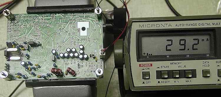
Don't panic! I know it's less than 1/2ma more than the last current measurement. I panicked, so now you don't have to. The FST3253 is rated at 3ua max quiescent current. This small increase was mostly due to measurement differences.
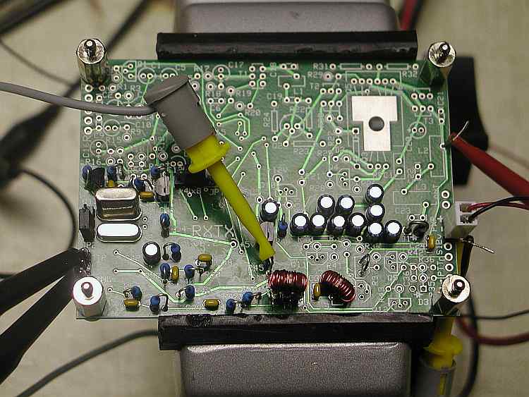
Hook the RF input to the top of L2 as shown. The 2 scope probes hook to the receiver tip and ring output. Connect the hairpin of R45 to ground. This unmutes the receiver and turns on the receiver mixer.
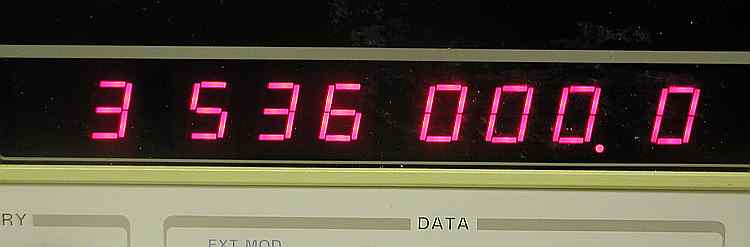
I have an RF input frequency of 3.536 MHz at 20 mv amplitude. I know, that's kind of hot for a receiver input but it sure makes it easier to look at with a scope and it's not overloading our board. Set JP1 to x8 and select one of your crystals with JP2.
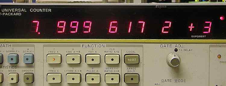
Here's the output frequency ready to go to the sound card. That's 7.99 KHz. Changing the RF frequency should give you a corresponding change in this frequency.
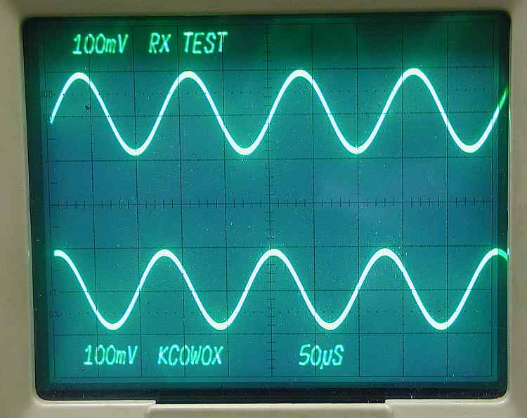
Here's the tip and ring I/Q signal. They are 90 degrees apart because mainly, they have to be because of the dividers. Next step, hook it to the computer.
Section 2 - The oscillator section
Section 3 - The divider section
Section 4 - T4 transformer build and test
Section 5 - Installing and testing the op amps
Section 6 - Installing and testing the mixer
Section 7 - Installing and testing the transmitter op amps
Section 8 - Installing and testing the transmitter mixer