Transmitter Op Amps
This is going to be one of the largest sections we will build. Actually, the left and the right channels are duplicates so it will be easily tested.
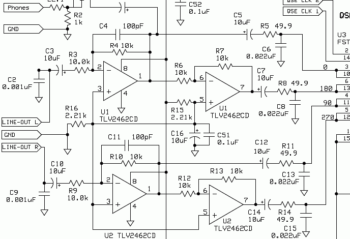
We need to install the following parts:
| R3, R4, R6, R7, R9, R10, R12, R13, | 10k ohm | resistor bag | |
| R15, R16 | 2.21k ohm | resistor bag | |
| R5, R8, R11, R14 | 49.9 ohm | resistor bag | |
| C4, C11 | 100 pfd | capacitor bag | |
| C3, C5, C7, C10, C12, C14, C16 | 10 ufd | capacitor bag | |
| C6, C8, C13, C15 | 0.022 | capacitor bag | |
| C2, C9, | 0.001 ufd | capacitor bag | |
| C51, C52 | 0.1 ufd | capacitor bag | |
| U1, U2 | TLV2462CD | IC bag |
We'll do this a little different because there are so many components.
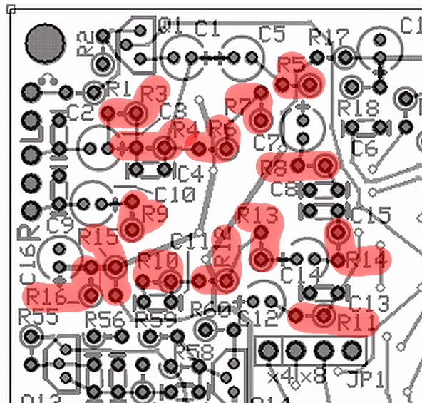
Install the resistors first.
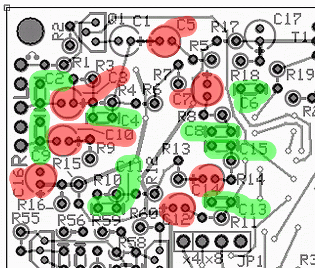
Install the capacitors
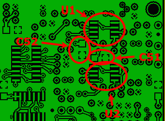
Install the chip caps and the IC's
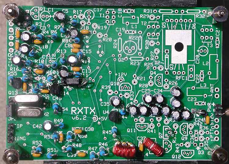
The board should now look like this.
We almost have all of the bottom components installed.
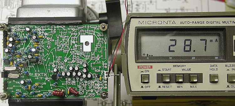
With 12.7 volts in, we read 28.7ma's.
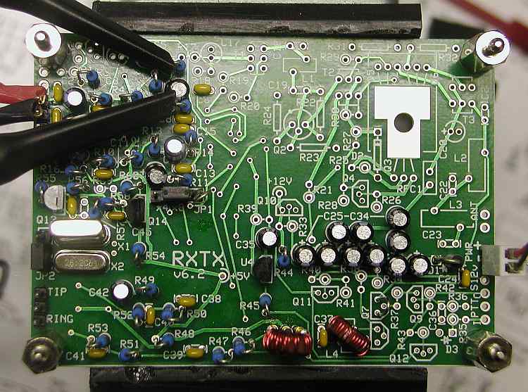
We are going to hook the scope probes to the hairpin on R5 and R8 for the Line-Out L channel and to R11 and R14 for the right channel. That's actually the left side of both resistors on the schematic but with U3 out, there is no current draw so no voltage drop through the resistors.
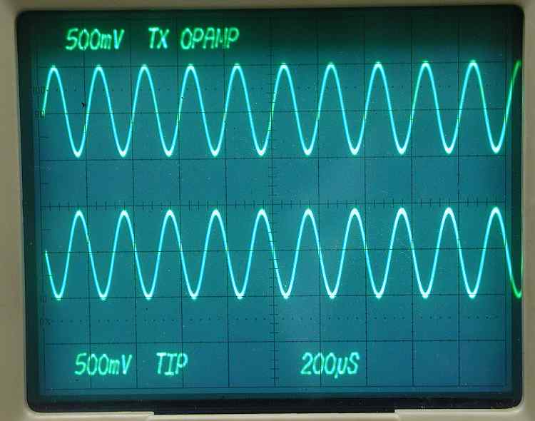
The op amp circuits are designed for a gain of 1 so we will input 1volt and we should see 1 volt out. The frequency can be just about anything in the range of the sound card. I used 5k for this picture.

The op amps will tolerate an input voltage of a little over 4 volts without distortion. Here I have about 4 volts in and I'm getting almost 4 volts out. This says 4 volts should be the maximum voltage out of the sound card.
Next step, install the mixer. Then we should begin to see RF again.
Section 2 - The oscillator section
Section 3 - The divider section
Section 4 - T4 transformer build and test
Section 5 - Installing and testing the op amps
Section 6 - Installing and testing the mixer
Section 7 - Installing and testing the transmitter op amps
Section 8 - Installing and testing the transmitter mixer