Receiver Op Amps
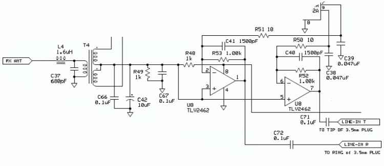
We are actually going to do this in 2 steps. Step 1, we will build starting from the RX ANT input and go to the right all the way to the left end of R48. Then we will input a signal and test T4 and the other parts we installed. First, lets sort out all of the parts we are going to use.
Step 1
| R48, R49 | 1.00 k resistors | resistor bag | |
| R50, R51 | 10 ohm resistors | resistor bag | |
| C24 | 560pfd | capacitor bag | |
| C37 | 680pfd | capacitor bag | |
| C38, C39 | 0.047ufd | capacitor bag | |
| C40, C41 | 1500pfd | capacitor bag | |
| C42 | 10ufd | capacitor bag | |
| C66, C67, C71, C72 | 0.1ufd | capacitor bag | |
| U8 | TVL2462 | IC bag | |
| L4 | 1.6uh | 19 turns #30 on a T30-2 red core - This is the smaller core. There are 4 of them in the kit. This will take 10" of the smaller wire | |
| T4 | See text |
Winding L4
Cut a 10" piece of the smaller wire. We are going to use one of the smaller red cores. There are 4 of them in the kit. I use a small bench vise to hold the core while I am winding it.
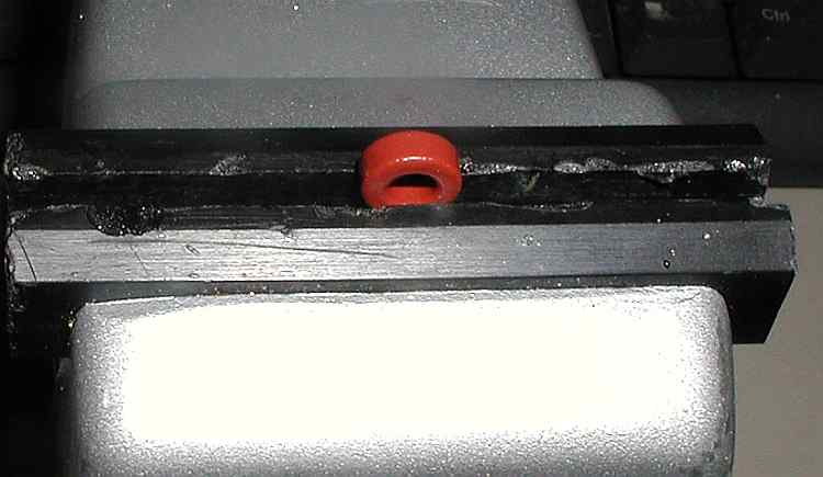
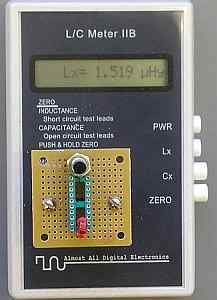
I wound 19 turns on the core initially and it measured 1.8uh. I removed 1 turn and the measured value dropped to 1.8uh. I removed 1 more turn leaving 17 and the result final was 1.519uh. 18 turns would probably be about optimal.
Winding T4
There is a 12 minute video demonstrating how to wind T4 at Winding T4
There's an additional 2 minute video on T4 specific winding at T4 special instructions
For 3 more basic videos on winding toroids and transformers
| Winding with torroid cores | |||
Selecting components and where to buy parts |
10 minutes |
183 meg | |
Measuring the winding results |
9 minutes |
116 meg | |
Winding a trifilar transformer |
10 minutes |
45 meg | |
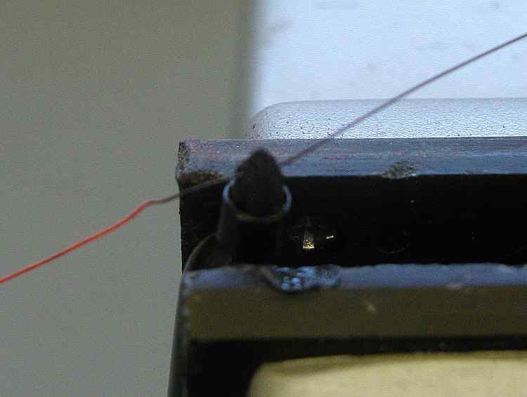
I can't take credit for this idea as I saw it on the internet somewhere. The easiest way to do transformer winding is to have several colors of wire. A work around is to take a sharpie, they come in many colors, and run the wire through a hole or slot in the tip. This will color the wire and help make windings easier to distinguish from each other. Here I have the "kink" for the center of my bifilar winding for the secondary of T4. The primary is already wound and the varnish stripped so I will be able to tell which one it is. The bifilar windings will be black and natural. You will be able to tell the natural one from the primary because it will be twisted with the black wire. I'm going to fold the wire back in half and then twist it about 3 turns to the inch.
Coloring the wire
After winding the primary I measured it. I read high in value so I removed 1 turn leaving a total of 16 turns instead of the called for 17 turns. Then I wound on the bifilar secondary of 8 turns.
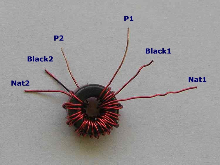
You can see remnants of the black coloring on the middle wires of each set. Since we are going the strip the enamel as the next step, trim the black ones so they are a little shorter than the others. This will make them eaiser to identify. In the picture, we have the primary wires next to each other, the short black wires in the middle, and the natural colored secondary windings at the 9 and 3 o'clock position. Now we strip. A piece of fine grit, cloth-backed, emery paper folded over works well to remove the enamel insulation.
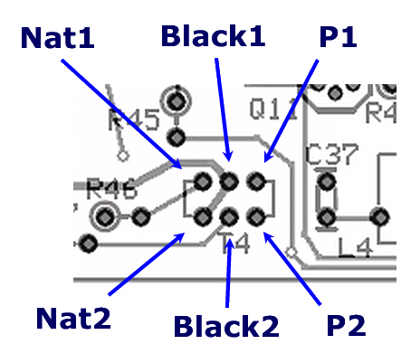
Install it on the board as shown
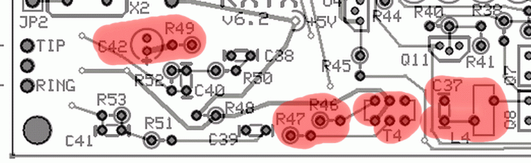
After installing T4, install the rest of these components.
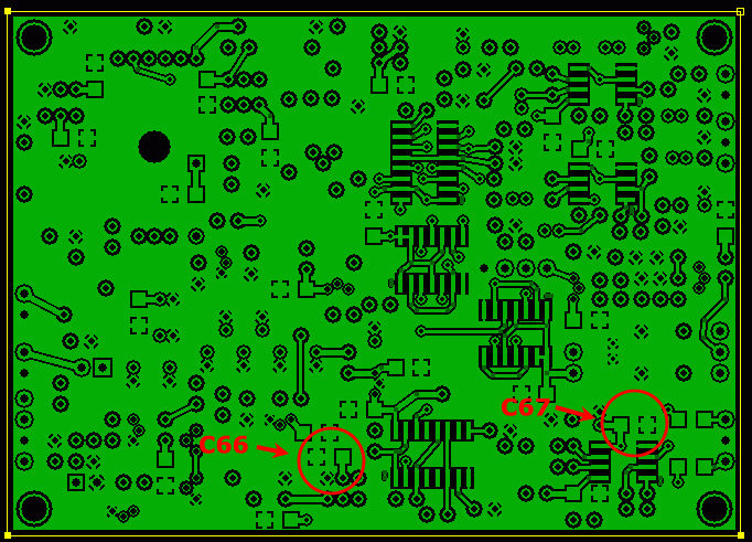
Install C66 and C67 on the bottom of the board.
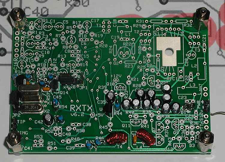
The top should now look like this.
The bottom now looks like this.
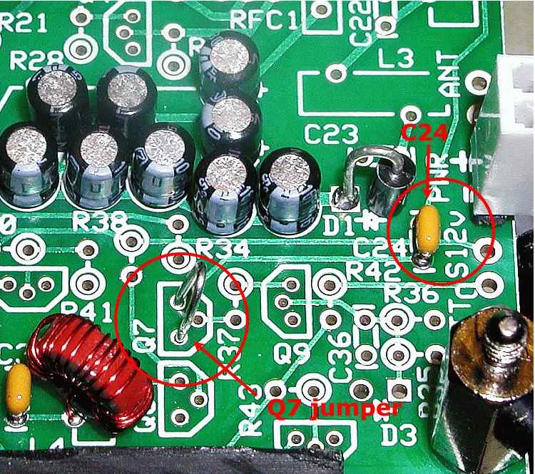
Before we can perform the following tests, we need to install 2 more things. First C24, and then a jumper from Q7 source to drain. You can probably just insert the wire without soldering it. I did. C24 is part of a frequency network made up of C24, L4, C37, and the primary of T4.
You do not apply power to perform these tests!
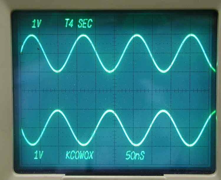
Input a couple of volt signal at around 7 MHz on the top right pad of L2. I used about 2.7 volts here. Once again, you can probably just use a cutoff component lead and poke it through the empty lead hole without soldering. Connect the scope probes to the hairpin on R46 and R47 and connect the probe ground leads to ground. Trigger your scope with channel 1. You shouls have an equal amplitude, opposite phase signal displayed. If they are in phase, you probably aren't triggering the scope on channel 1. If either one is missing, double chect the solder connections for T4.
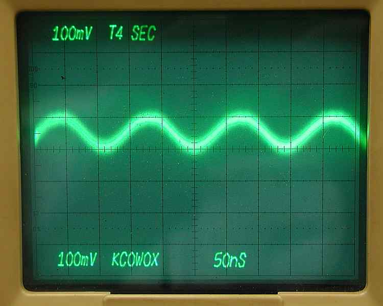
Notice the volts/div amplitude change. This is a way to test the amplitude balance of your transformer T4. Using the scope vertical plugin add function, add the 2 out-of-phase signals together. If they would have been perfectly matched, the difference would have been zero. Here we see a difference of about 100mv. Thats a 5% error. I think I can live with that. The software should be able to compensate for that.
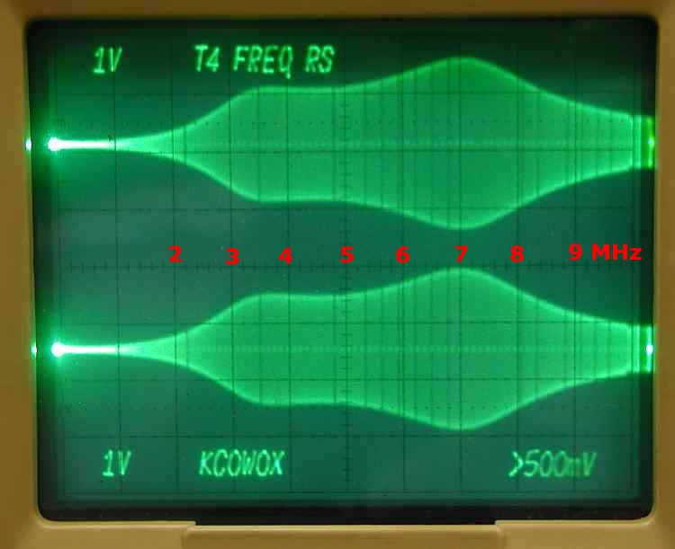
Here I'm sweeping from 0 MHz to 10 MHz. Each horizontal division represents 1 MHz. The difference in response between the 3 volts of 7 MHz and 2 volts of 3.5 MHz are only about 3.5db so is really no big deal.
Section 2 - The oscillator section
Section 3 - The divider section
Section 4 - T4 transformer build and test
Section 5 - Installing and testing the op amps
Section 6 - Installing and testing the mixer
Section 7 - Installing and testing the transmitter op amps
Section 8 - Installing and testing the transmitter mixer