Introduction
This stage develops the receiver's RF path to be fed, ultimately to the RX mixer stage. The path involves a bandpass filter and a coupling transformer. The gotchas in this stage are mostly with respect to the inductors: the winding of the inductors and the clean soldering of their leads to the board in the proper orientation.If you are new at this stuff, check out the tutorial videos and experts' notes on winding toroids.
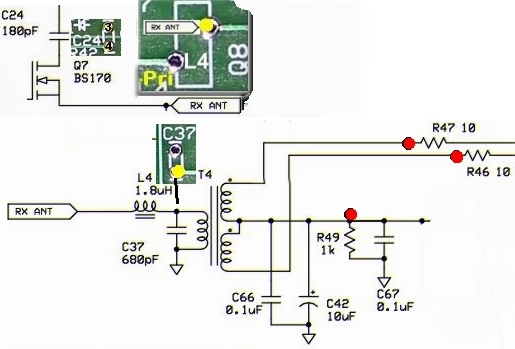
Schematic
Bill of Materials
| Designation | Value | Orientation |
|---|---|---|
| C24 | 180pF, ceramic, 5% | n/a |
| C37 | 680pF, ceramic, 5% | n/a |
| C42 | 10uF/16 VDC Electrolytic | South-North |
| C66 | 0.1uF, smt 1206 | smt |
| C67 | 0.1uF, smt 1206 | smt |
| L04 | T30-6 (yellow) (#30) (1.8 uH) | 22T |
| R46 | 10.0, 1/4 W, 1% | West-East |
| R47 | 10.0, 1/4 W, 1% | West-East |
| R49 | 1.00 K, 1/4 W, 1% | East-West |
| T04 | T30-6 (yellow) (#30) (0.44 uH) | 11T/2x5T |
| Test1 | shunt wire for Q7 source-drain | n/a |
Build Notes
- Install the 2 ceramic capacitors (C24 and C37) and the electrolytic cap (C42)
- Install the 3 resistors (R46, R47, R49)
- Install the 2 SMT caps (C66 and C67) on the bottom of the board - watch out with each - a shaky hand could lead to a solder blockage of the adjacent component thru-holes; use a sharp-pointed toothpick to temporarily shield the hole from solder leakover
- Wind and install T4 - notice the placement of the primary leads and the two secondary windings' leads (P, S1, and S2 in the diagram above)
- Wind and install L4
Testing
T4 Resistance Checks
First, test the resistance WRT ground of the RX ANT connection
- Apply the ohmmeter probe to the top left hand hole of L4
- clip the other probe to the ground wire loop at JP1
- resistance of close to zero indicates that L4 and T4's primary leads have been soldered OK
Next, test the secondary connections of T4
- keep the ohmmeter's ground connection
- measure the resistance at the R46 hairpin - it should be 1K ohm;
- measure the resistance at the R47 hairpin - it should be 1K ohm
T4 Balance
Input a couple of volt signal at around 7 MHz on the top right pad of L2. I used about 2.7 volts here. Once again, you can probably just use a cutoff component lead and poke it through the empty lead hole without soldering. Connect the scope probes to the hairpin on R46 and R47 and connect the probe ground leads to ground. Trigger your scope with channel 1. You should have an equal amplitude, opposite phase signal displayed. If they are in phase, you probably aren't triggering the scope on channel 1. If either one is missing, double check the solder connections for T4.