Introduction
The second stage is the Local Oscillator. The circuit must provide the clock signal that is 4 times the desired center frequency. In the 40/30m kit, the two output frequencies correspond to the 2 crystals supplied:
- 40m: 28.06 MHz or 28.224 MHz,respectively, for 7.015 MHz or 7.056 MHz center frequency
- 30m: 40.5 MHz for the 10.125 MHz center frequency
- Mounting the crystals and attaching their ground straps.
- Soldering the leads on the transistors, Q13 and Q14. They are mounted to conform to the shape on the board silkscreen, After soldering the leads, double check them for solder bridges.
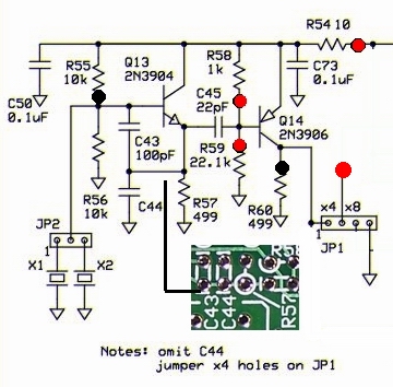
Schematic
Bill of Materials
| Designation | Value | Orientation |
|---|---|---|
| C43 | 100pF, ceramic, 5% | n/a |
| C45 | 22pF, ceramic, 5% | n/a |
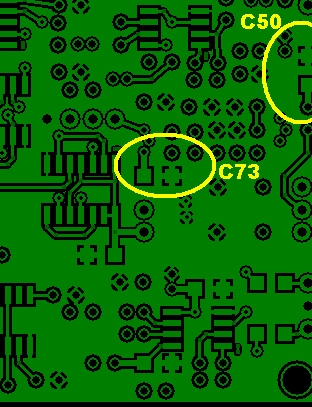
| C50 | 0.1uF, smt 1206 | smt |
| C73 | 0.1uF, smt 1206 | smt |
| JP2 | 2-pin hdr & jumper plug | n/a |
| Q13 | 2N3904 NPN | TO 92 |
| Q14 | 2N3906 PNP | TO 92 |
| R54 | 10.0, 1/4 W, 1% | North-South |
| R55 | 10.0 K, 1/4 W, 1% | North-South |
| R56 | 10.0 K, 1/4 W, 1% | West-East |
| R57 | 499, 1/4W, 1% | South-North |
| R58 | 1.00 K, 1/4 W, 1% | West-East |
| R59 | 22.1 K, 1/4W, 1% (omit for 40/80) | West-East |
| R60 | 499, 1/4W, 1% | West-East |
| X01 | 28.06 MHz and / or 28.224 MHz | n/a |
| X02 | 40.5 MHz | n/a |
Build Notes
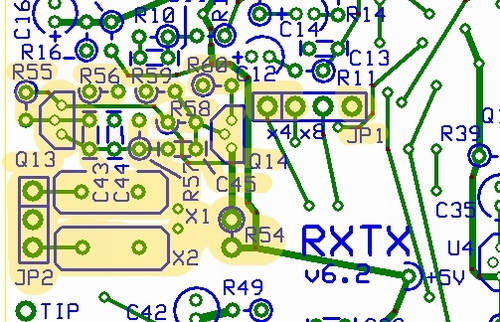
JP1
Mount a small wire loop to bridge the x4 holes, holes 1 and 2, of JP1. (This will result in each crystal frequency being divided by four in the clocking of the QSD and QSE circuits. The center frequency resulting from the x4 jumper will be approximately the crystal frequency divided by four) .
Testing
Current Draw
- Initially, place a current limiting 1K resistor in series with one of the power leads,
- apply 12 Vdc power
- measure the current draw.
- You should see less than 10 mA draw. If the draw is greater than 10 mA, you should check your circuit for a short.
- Remove the current limiting resistor
- apply 12 Vdc power
- measure the current draw.
- The result should be around 11.5 mA.
- Set the ammeter back to voltage
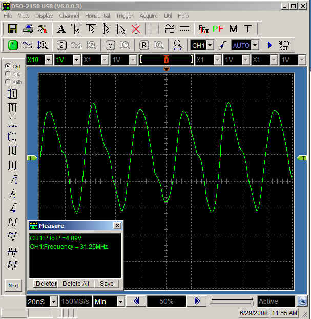
Oscillator Output Waveform
- Connect your scope lead to the left-hand loop on JP1 and the ground clip to the right hand loop.
- Use the jumper and JP2 to select one or the other of the crystals.
- Power up and observe the trace on the scope.
- Depending upon the crystal selected, you should see a sinusoidal wave approximately 4.5 V p-p and frequency of 40.5, 28.224, or 28.060 MHz