Introduction
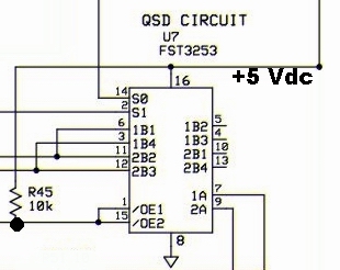
This stage completes the RX portion of the project. The Mixer (actually a high-speed mux/demux switch) samples the RF with the sampling clock driven by the outputs of the quadrature divider stage. The resultant samples are integrated and fed to the OpAmps and thence, to the PC's sound card. Once the Mixer is installed, the board's RX functionality is built.Schematic
Bill of Materials
| Designation | Value | Orientation |
|---|---|---|
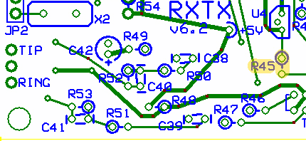
| R45 | 10.0 K, 1/4 W, 1% | North-South |
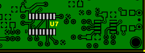
| U07 | FST3253 or SN74CBT3253D | SOIC 16 |
Build Notes
Testing
Current Draw
- With 1 k limiting resistor:
- without limiting resistor (s/b 0.5 mA greater than previous stage)
Mixer Pin Voltages
| Pin | Expected Value | Author Result | Measured As |
|---|---|---|---|
| 1 (R45 hairpin) | 0 Vdc | 0 | |
| 2 | 2.5 Vdc | 2.46 | |
| 3 | 2.5 Vdc | 2.39 | |
| 6 | 2.5 Vdc | 2.38 | |
| 7 | 2.5 Vdc | 2.38 | |
| 8 | 0 (gnd) | 0 | |
| 9 | 2.5 Vdc | 2.38 | |
| 11 | 2.5 Vdc | 2.38 | |
| 12 | 2.5 Vdc | 2.39 | |
| 14 | 2.5 Vdc | 2.45 | |
| 15 (R45 hairpin) | 0 Vdc | 0 | |
| 16 | 5 Vdc | 4.96 | |
RF Injection Test
- shunt the top and bottom holes of Q7
- Connect the hairpin of R45 to ground. This unmutes the receiver and turns on the receiver mixer.
- Hook the RF input to the top of L2 as shown. I tap into the output of the MFJ Antenna Analyzer operating into a 50 ohm dummy at ~7.040 MHz
- Connect the 2 scope probes to the receiver tip and ring output.
- Select the 28.224 MHz Xtal (center freq=7.056 MHz
- Observe the signals on the scope. You should see 2 signals 90 degrees out of phase and frequency of 16 kHz
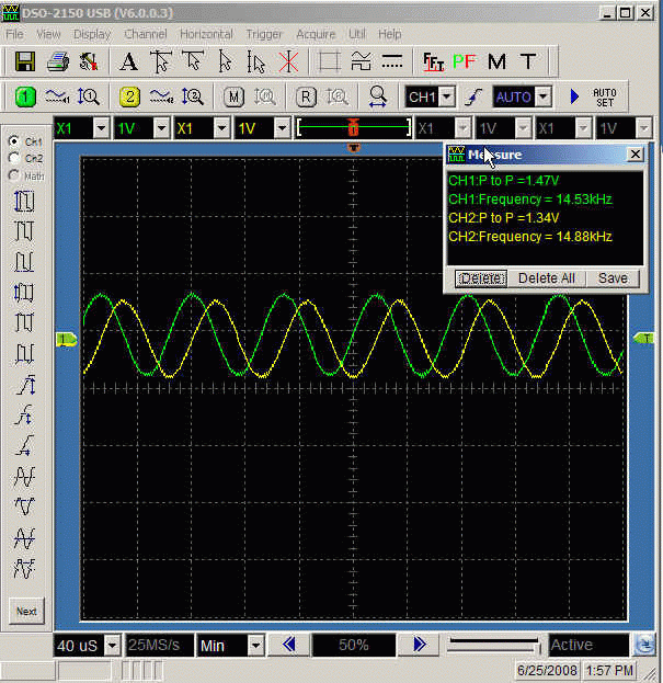
(customary caveat on scope's accuracy)