Introduction
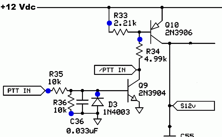
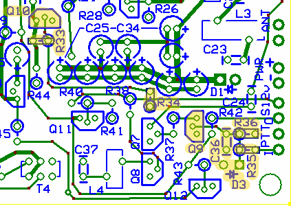
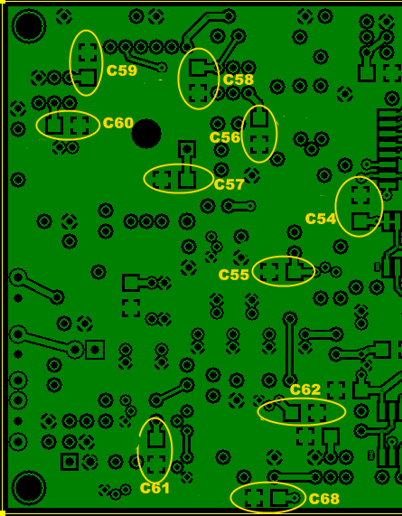
This stage was arbitrarily chosen as the place to go ahead and install the remaining SMT capacitors (now that the SMT ICs have all been installed).This and the next three stages wrap up some miscellaneous enabling functionality to handle switching between RX and TX and to provide audio listening) output for the board, should that be desired.
Schematic

Bill of Materials
| Designation | Value | Orientation |
|---|---|---|
| C54 | 0.1uF, smt 1206 | smt |
| C55 | 0.1uF, smt 1206 | smt |
| C56 | 0.1uF, smt 1206 | smt |
| C57 | 0.1uF, smt 1206 | smt |
| C58 | 0.1uF, smt 1206 | smt |
| C59 | 0.1uF, smt 1206 | smt |
| C60 | 0.1uF, smt 1206 | smt |
| C61 | 0.1uF, smt 1206 | smt |
| C62 | 0.1uF, smt 1206 | smt |
| C68 | 0.1uF, smt 1206 | smt |
| C36 | 0.033uF, ceramic, 10% | n/a |
| D3 | 1N4003 | West-East (cathode=hairpin) |
| Q09 | 2N3904 NPN | TO 92 |
| Q10 | 2N3906 PNP | TO 92 |
| R33 | 2.21 K, 1/4W, 1% | East-West |
| R34 | 4.99 K, 1/4W, 1% | South-North |
| R35 | 10.0 K, 1/4 W, 1% | West-East |
| R36 | 10.0 K, 1/4 W, 1% | West-East |
Build Notes

- When mounting D3, mount it so the lead going to the square pad (cathode) is a hairpin style lead
- Be sure to distinguish between the 2N3904 and the 2N3906 (the markings look very similar).

| Designation | Value | Orientation |
|---|---|---|
| C54 | 0.1uF, smt 1206 | smt |
| C55 | 0.1uF, smt 1206 | smt |
| C56 | 0.1uF, smt 1206 | smt |
| C57 | 0.1uF, smt 1206 | smt |
| C58 | 0.1uF, smt 1206 | smt |
| C59 | 0.1uF, smt 1206 | smt |
| C60 | 0.1uF, smt 1206 | smt |
| C61 | 0.1uF, smt 1206 | smt |
| C62 | 0.1uF, smt 1206 | smt |
| C68 | 0.1uF, smt 1206 | smt |
Testing
Current Draw
- With current limiting resistor:
- Without current limiting resistor you should see ~38 mA
Switching
- Before powering up, attach a clip lead between the hairpin of R33 and the hairpin of R35 (this sets PTT_IN = 12 Vdc, ON)
- Apply power
- Measure the voltage at the hairpin of R34. You should get 9-10 Vdc
- Measure the voltage at the S12V pad. You should get a high signal ~12 Vdc (can go as low as 10 Vdc, depending upon battery)
- Unclip the lead at the R33 hairpin (this sets PTT OFF)
- Measure the voltage at R34 again. You should get 9-10 Vdc
- Measure the voltage at the S12V pad again. You should get a low signal, ~0 Vdc