Introduction
Theory of Operation
This stage lets the SDR filter out the RF spectrum arriving at the antenna into a "chunk" of the RF spectrum corresponding to the desired band(s). This is filtering "in the large", and is designed to minimize interference/harmonics from very strong, out-of-band signals.
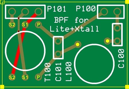
There are four separate, pluggable boards which can be built to provide BPF functionality over the range from 160m to 10m.
Note: the pluggable bandpass filters may be replaced by the new switchable HF BPF board kit, which implements 4 switchable BPFs on a single board, which can be manually switched or (once firmware is updated) switched via USB control.
Bill of Materials
| Designation | Value | Color/Code | Orientation | Category | Notes |
|---|---|---|---|---|---|
| - | |||||
| BPF-1 | 160m board | ||||
| P100-1 | 2 pin | ||||
| P101-1 | 3 pin | ||||
| C100-1 | 390 pF | 391 | ceramic | ||
| C101-1 | 5600 pF | 562 | ceramic | ||
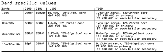
| T100-1 | 1.4 uH | T30-2 (red) | 18T/9T bifilar #30 (10"/5") | ||
| L100-1 | 18.7 uH | T30-2 (red) | 66T #30 (32") | ||
| - | |||||
| BPF-2 | 80/40m board | ||||
| P100-2 | 2 pin | ||||
| P101-2 | 3 pin | ||||
| C100-2 | 560 pF | 561 | ceramic | ||
| C101-2 | 680 pF | 681 | ceramic | ||
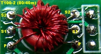
| T100-2 | 1.2 uH | T25-2 (red) | 18T/9T bifilar #30 (10"/5") | ||
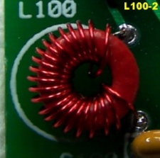
| L100-2 | 1.6 uH | T25-2 (red) | 22T #30 (11") | ||
| - | |||||
| BPF-3 | 30/20/17m board | ||||
| P100-3 | 2 pin | ||||
| P101-3 | 3 pin | ||||
| C100-3 | 180 pF | 181 | ceramic | ||
| C101-3 | 220 pF | 221 | ceramic | ||
| T100-3 | 0.6 uH | T25-6 (yellow) | 14T/7T bifilar #30 (8"/5") | ||
| L100-3 | 0.78 uH | T25-6 (yellow) | 17T #30 (9") | ||
| - | |||||
| BPF-4 | 15/12/10m board | ||||
| P100-4 | 2 pin | ||||
| P101-4 | 3 pin | ||||
| C100-4 | 82 pF | 82 | ceramic | ||
| C101-4 | 330 pF | 331 | ceramic | ||
| T100-4 | 0.13 uH | T25-6 (yellow) | 7T/4T bifilar #30 (5"/4") | ||
| L100-4 | 0.53 uH | T25-6 (yellow) | 14T #30 (8") |
Summary Build Notes
- Cut the provided board into 4 BPF boards.
- For each desired band pass filter board (BPF-#):
- Install pins to board bottom
- Install ceramic caps to topside
- Wind and install inductors
- Test the stage
Detailed Build Notes
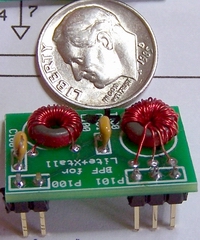
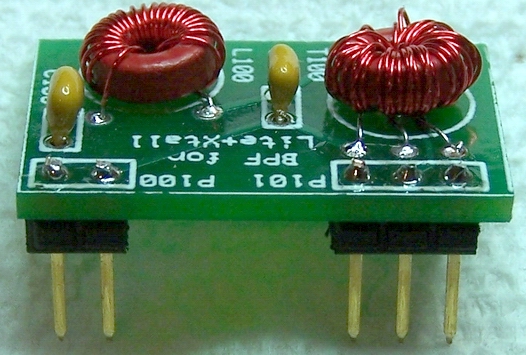
There are four bandpass filters (BPFs) you can build, each on its own board with 2 caps, a coil, a transformer, and two sockets for plugging it into the main board. The Bill of Materials above provides you with the parts list for each board. You only need to build one BPF to test out your receiver capability. It is recommended - especially if you are inexperienced in winding coils and toroids - to begin with a BPF for the band you are least interested in (just to get the practice in a non-threatening fashion).
Saw The Boards
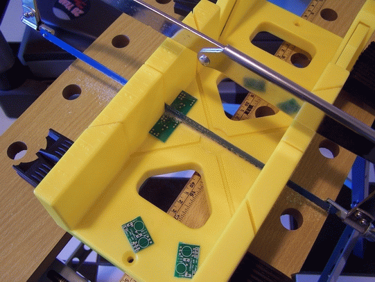
The BPF filter boards are in a strip of four boards and will require the kit builder
to hacksaw between the boards to separate the individual BPF boads. It is suggested
to use a small plastic miter box and a fine-toothed blade (24 tpi or better) to help cut perpendicularly across the 0.65 inch
wide strip. This seems to work well. However, please note the
safety warnings on the Softrock reflector (message 23126) concerning the danger in inhaling the dust
resulting from sawing.
Winding Inductors
To learn how to wind coils and transformers, please read the tips from the experts and then view the excellent videos on KC0WOXs Website to solidify your understanding of the task.
Concernimg the number of turns in the windings, David WW2R has reported that he had to adjust the number of windings on L100-1 (the 66 turn coil on the 160m band) because of the fact that the toroid was not able to accept 66 turns as a single layer, without winding back over some of the existing winding. Overlapping turns caused him to need 69 turns to reach the required inductance of 18.7 uH.
Pete N4ZR chimed in on this subject, too, adding: "The 160-meter L100 requires 66 turns, but only about 40-45 turns will fit on the core in a single layer. You need to keep winding in the same direction in a second layer until you complete the 66-69 turns. I wound 69 originally, but on checking with my MFJ-259, which may not be very accurate the inductance appeared to be a little high.
When winding bifilar windings, it is a lot easier to wind the bifilar winding if you fold the wire in half but don't cut, and use the folded (closed) end (with or without a sewing needle) to feed through the toroid or binocular core.
Wire Lengths
:Refer to the BOM above to see the recommended length of wire (in inches) for each inductor. These lengths include generous SWAGS to accomodate lead lengths, etc.. These were determined using DL5WWB's calculator (adding an inch or so to the resultant length, just for good measure.
When the BOM states BPF-80/40: 18T/9T bifilar #30 (10"/5") this means:
- Primary: 18 turns of #30, using 10" for the single winding.
- Secondaries: 9 turns of #30, using a 10" length of wire and fold it over at the 5" point, twisting it together into a bifilar strand, winding it evenly distributed over the primary winding for 9 turns. The bifilar strand should be about two-three twists per inch.
Core Sizes
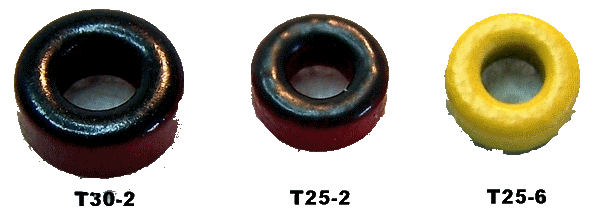
: The chart below provides the capacitance values and the winding instructions by band group. Carefully note that some bands use different size and color cores. Be sure to use the right core for the board you are building:- 160 m: T30-2 (red)
- 80/40m: T25-2 (red)
- 30/20/17/15/12/10m : T25-6 (yellow)
For Each BPF Board
(referring to the Band Specific Values chart, above):
| Check | Designation | Type | Notes |
|---|---|---|---|
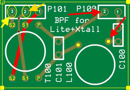
| L100-# | Coil |
Wind, prepare, horizontally mount, and solder the coil, L100, using the
correct core size and color and turn count..
|
|
| T100-# | Transformer |
Wind, prepare, horizontally mount, and solder the transformer, T100
|
|
| C100-# | ceramic capacitor | Mount and solder the capacitor, C100 | |
| C101-# | ceramic capacitor | Mount and solder the capacitor, C101 | |
 | |||
| P100-# | 2 pin header | Mount and solder the 2-pin header, P100, on the underside of the board, with the shorter pins going through the holes from the bottomside to the topside and the longer pins extending out from the bottom side to mate with the main board (2). | |
| P101-# | 3-pin header | Mount and solder the 3-pin header, P101, on the underside of the board, with the shorter pins going through the holes from the bottomside to the topside and the longer pins extending out from the bottom side to mate with the main board. (2) |
1 The L-100 for the 160m BPF will require overlapping the windings in order to fit all of them on the toroid. The first layer pretty well fills up after 45 or so turns.
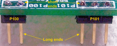
2 The BPF board connectors (P100 and P101 headers)
are mounted, short ends into the holes for P100-# and P101-#,
on the bottom of the board with the other components on top.
Use the main board 9-pin socket (J1) as a "tool" to align the pin headers
on each BPF board so that the two will mate properly.
Completed Board (80/40m)
Testing
Continuity
Test T100 Primary Resistance
- Using your ohmmeter, measure the resistance from The C100 hole farthest away from P100 to ANT Return. It should be ~0 ohms, indicating continuity in the primary windings of T100, through the L100 windings.
- If you get any appreciable resistance or an open circuit, you should inspect/touch up the solder joints on T100 primary and/or L100.
Test T100 Secondaries Resistance
- Using your ohmmeter, measure the resistance between pins 2 and 3 of P101.
It should be ~0 ohms, indicating continuity between the ends of the two secondary windings and through the center tap. - If you get any resistance or an open circuit, you should inspect and/or touch up the solder joints.
- Note: that the two secondaries are center-tapped so both windings are "connected" continuously in the circuit from pin 2 to pin 3.