Introduction
Theory of Operation
This stage amplifies the quadrature audio frequency difference products from the
Mixer stage via R17 and R18. R19 and R20 make up a voltage divider that provides
the 2.5 Vdc bias to the Op-Amps, configured as an inverting amplifier. The ratios
of R19/R17 and R20/R18, respectively, determine the voltage gain of the output over
the input for each Op-Amp. That voltage gain is theoretically 499:1, or about 54
dB. Each Op-Amp's output is capacitively coupled through a 100 ohm resistor to the
"Ring" (Q) and "Tip" (I) Audio Out terminals for input to the PC's sound card
Schematic
This is a subset of the
overall schematic.
Note: red dot indicates resistor testpoints (hairpin, top, or left-hand lead)
Bill of Materials
| Designation | Value | Color/Code | Orientation | Category | Notes |
|---|
| U8 | LT6231CS8 | | 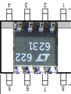 | SMT | |
| C31 | 0.1uF | | | SMT 1206 | black marked strip |
| C32 | 0.1uF | | | SMT 1206 | black marked strip |
| C28 | 0.1uF | | | SMT 1206 | black marked strip |
| C25 | 0.1uF | | | SMT 1206 | black marked strip |
| R17 | 10 |  | W-E | | |
| R18 | 10 | | flat-h | | |
| R15 | 1k |  | flat-h | | |
| R16 | 1k | | W-E | | |
| R19 | 4.99k |  | E-W | | |
| R20 | 4.99k | | flat-h | | |
| R21 | 100 |  | flat-v | | |
R22 | 100 | | flat-h | | | C26 | 0.047uF | 473 | | ceramic | |
| C27 | 0.047uF | 473 | | ceramic | |
| C29 | 220pF | 221 | | ceramic | |
| C30 | 220pF | 221 | | ceramic | |
| C24 | 4.7uF | 475 | | ceramic | |
Summary Build Notes
- Install SMT IC U8 (bottom)
- Install 4 x 0.1 µF SMT capacitors (bottom)
- Install 8 resistors R15-R22 (top)
- Install 5 ceramic capacitors C24 and C26-C30(top)
- Test the Stage
Detailed Build Notes
Bottom of the Board
Install U8
| Designation | Value | Color/Code | Orientation | Category | Notes |
|---|
| U8 | LT6231CS8 |
|
|
SMT SOIC-8 | |
Install SMT Caps
| Designation | Value | Color/Code | Orientation | Category | Notes |
|---|
| C31 | 0.1uF | | | SMT 1206 | black marked strip |
| C32 | 0.1uF | | | SMT 1206 | black marked strip |
| C28 | 0.1uF | | | SMT 1206 | black marked strip |
| C25 | 0.1uF | | | SMT 1206 | black marked strip |
Top of the Board
Install Resistors
| Designation | Value | Color/Code | Orientation | Category | Notes |
|---|
| R17 | 10 | | W-E | | |
| R18 | 10 | | flat-h | | |
| R15 | 1k | | flat-h | | |
| R16 | 1k | | W-E | | |
| R19 | 4.99k | | E-W | | |
| R20 | 4.99k | | flat-h | | |
| R21 | 100 | | flat-v | | |
R22 | 100 | | flat-h | | |
Install Ceramic Capacitors
| Designation | Value | Color/Code | Orientation | Category | Notes |
|---|
| C26 | 0.047uF | 473 | | ceramic | |
| C27 | 0.047uF | 473 | | ceramic | |
| C29 | 220pF | 221 | | ceramic | |
| C30 | 220pF | 221 | | ceramic | |
| C24 | 4.7uF | 475 | | ceramic | |
Completed Stage
Topside
Bottomside
Testing
Current Draw(DMM)
- Current numbers here are for the CMOS version of the Si570. You will need
to adjust these up by about 14 mA for the LVDS version.
- Power the board up
- Measure the current draw and 5 V rail voltage with a 1K Ω limiting resistor
- Measure the current draw without the limiting resistor.
| Testpoint | Nominal Value | Author's | Yours |
|---|
| Current Limited mA | 6-10 mA | 7.5 mA | ______ |
| Current limited 5V rail | 1-2 Vdc | 971 mV | ______ |
| Non limited draw mA | 90-100 mA | 94.9 mA | ______ |
#voltage_divider_test
Voltage Divider R15/R16(DMM)
- Measure the voltage at the R16 hairpin lead with respect to ground.
- It should read approximately 2.5 Vdc (½ the 5 volt rail).
| Testpoint | Nominal Value | Author's | Yours |
|---|
| R16 hairpin lead | 2.5 Vdc | 2.48 Vdc | ______ |
Pin Voltages (DMM - 5, 2.5, and 0 Vdc)
- Measure the voltages at the pins of U8.
(see bottomside image above)
- It is best to test for pin voltages at the actual pins (not the pads), thereby ensuring
correct soldering of the pins to the pads.
| Testpoint | Nominal Value | Author's | Yours |
|---|
| U8, Pins 1, 2, 3, 5, 6 & 7 | 2.5 Vdc | 2.48-2.51 Vdc | ______ |
| U8, Pin 8 | 5 Vdc | 4.96 Vdc | ______ |
| U8, Pin 4 | 0 Vdc | 0 Vdc | ______ |
OpAmp Test - DMM (No Scope)
Tony Parks suggested this next test,which requires only a DMM, a 10 k
resistor, and some clip leads.
The test will test each of the two Op-Amps.
If the Op-Amp being tested is working, then the voltage measured at the output of
the Op-Amp will increase to accomodate the effect of the changed bias on the input.
Passing these tests gives you more than enough confidence to move on to the Mixer
stage.
- Obtain a 10k resistor (you can use R11 from the next stage's BOM)
- using the DMM, measure the dc voltage with respect to ground
at the hairpin of R19.
The result should be approximately 2.5 Vdc (½ the 5 Vdc rail).
- keep the DMM lead on R19's hairpin
- Using two clip leads, "bridge" the 10k resistor between the hairpin of R17
and ground.
See the diagram to the left.
- Observe the voltage reading at R19 hairpin. If OpAmp 1 is working, the voltage should
have jumped to approximately 3.75 Vdc
- Remove the resistor/clip lead from R17 and the voltage at R19 should go back to
the 2.5 Vdc level.
- Follow these same steps for OpAmp2, substituting:
- R18 (right-hand lead) for R17 (hairpin) and
- R20 (left-hand lead) for R19 (hairpin).
| Testpoint | Nominal Value | Author's | Yours |
|---|
| R19 hairpin - no bridge | 2.5 Vdc | 2.51 Vdc | ______ |
| R19 hairpin - R17 bridged | 3.75 Vdc | 3.75 Vdc | ______ |
| R20 left-hand lead - no bridge | 2.5 Vdc | 2.51 Vdc | ______ |
| R20 left-hand lead - R18 bridged | 3.75 Vdc | 3.75 Vdc | ______ |