Introduction
Theory of Operation
This stage provides the two power rails for the radio:
- a regulated +3.3 Vdc for the local oscillator stage
- a regulated +5 Vdc for the divider, mixer, and opamp stages
Note that the USB stage is powered from the PC's USB port's +5Vdc
Schematic
This is a subset of the overall schematic.
Bill of Materials
| Designation | Value | Color/Code | Orientation | Category | Notes |
|---|---|---|---|---|---|
| U3 | LP2992AIM5-3.3V | LFEA | 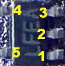 | SMT | marked "LFEA" |
| C12 | 0.01uF | SMT 1206 | |||
| C13 | 0.01uF | SMT 1206 | |||
| C15 | 0.01uF | SMT 1206 | |||
| C02 | 0.1uF | SMT 1206 | black marked strip | ||
| C03 | 0.1uF | SMT 1206 | black marked strip | ||
| C09 | 0.1uF | SMT 1206 | black marked strip | ||
| C10 | 0.1uF | SMT 1206 | black marked strip | ||
| C01 | 4.7uF | 475 | ceramic | ||
| C04 | 4.7uF | 475 | ceramic | ||
| C11 | 4.7uF | 475 | ceramic | ||
| C14 | 4.7uF | 475 | ceramic | ||
| D1 | 1N4003 | W-E | |||
| U1 | LM7805 | 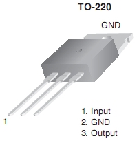 | |||
| J2 | 3 pin |
Summary Build Notes
- Install SMT ICs and Capacitors (bottom)
- Install ceramic capacitors (top)
- Install D1 (top)
- Install U1 (top)
- Install power bus jack, J2
- Test the Stage
Detailed Build Notes
Bottom of the Board
The challenge here is the extremely tiny 3.3V regulator, U3. Be very careful tweezing this component, as, if it ever gets launched into space, it will be nigh on impossible to find.
Also be careful to note the two different types of SMT caps. There are three 0.01 uF caps and four 0.1 uF caps, the latter being identified by a black stripe drawn on the plastic carrier strip.
Install SMT ICs and Caps
Do not confuse U3, marked "LFEA", with the FIN 1002 (U5) marked "FN02X"
| Designation | Value | Color/Code | Orientation | Category | Notes |
|---|---|---|---|---|---|
| U3 | LP2992AIM5-3.3V | LFEA |
|
SMT SOT-23 |
Install Five pin SMT 3.3V Voltage Regulator, U3, to bottom of board.
Make sure U3 leads are well-centered on their pads, then tack the
IC in place by careful soldering of one lead. Apply heat to pin to reposition
U3 and, when properly positioned, carefully solder the other leads.
Use solder wick to remove excess solder or solder bridges between pins
|
| C12 | 0.01uF | SMT 1206 | |||
| C13 | 0.01uF | SMT 1206 | |||
| C15 | 0.01uF | SMT 1206 | |||
| C02 | 0.1uF | SMT 1206 | black marked strip | ||
| C03 | 0.1uF | SMT 1206 | black marked strip | ||
| C09 | 0.1uF | SMT 1206 | black marked strip | ||
| C10 | 0.1uF | SMT 1206 | black marked strip |
Top of the Board
Install Ceramic Caps
| Designation | Value | Color/Code | Orientation | Category | Notes |
|---|---|---|---|---|---|
| C01 | 4.7uF | 475 | ceramic | ||
| C04 | 4.7uF | 475 | ceramic | ||
| C11 | 4.7uF | 475 | ceramic | ||
| C14 | 4.7uF | 475 | ceramic |
Install Diode and U1
| Designation | Value | Color/Code | Orientation | Category | Notes |
|---|---|---|---|---|---|
| D1 | 1N4003 |

|
W-E | Hairpin style with the hairpin on the cathode lead | |
| U1 | LM7805 |
|
Mount 5V Voltage regulator U1, LM7805, to top of board with a
4-40 machine screw,
#4 start lockwasher,
and hex nut, attaching the tab of U1 to the board
|
Install Power Bus Jack J2
| Designation | Value | Color/Code | Orientation | Category | Notes |
|---|---|---|---|---|---|
| J2 | 3 pin |
Completed Stage Photos
BottomSide
Topside
Testing
Current Draw
Test Setup
- To power the v9.0 receiver you will need a 9 volt to 12 volt DC source at a little over 100 mA. A supply that is free of ground connnections works best.
- Before you power the board up for the first time, connect a mA meter in series with the power lead and to be safe, put a 1k ohm resistor in series with the power lead. This can be in either the + or - line. This will limit the current flow to <=12 mA if you have a short on the board.
- After you see that the current isn't excessive, remove it, and re-measure the current draw.
- The current draw with this initial stage and no other loads should be < 5 mA
Test Measurements
| Testpoint | Nominal Value | Author's | Yours |
|---|---|---|---|
| Current draw thru 1 k limiting resistor | 3-5 mA | 3.1 mA | ______________ |
| Current draw without limiting resistor | 3-5 mA | 3.2 mA | ______________ |
Voltages
Test Setup

- Power up the board with 12 Vdc
- Using a DMM, measure the voltages with respect to ground (ground = J2 pin 1).
- The 12 volt rail should be be approximately 12 volts DC. It should show a voltage drop from the power source on the order of .5 to .7 Vdc, representing the effect of D1's ohmic resistance in the circuit.
Test Measurements
| Testpoint | Nominal Value | Author's | Yours |
|---|---|---|---|
| 3.3 V Rail: R7 body hole (see above) | 3.3 Vdc | 3.29 | ____________ |
| 5 V Rail: J2-Pin2 | 5 Vdc | 4.97 Vdc | ____________ |
| 12 V Rail: J2-Pin3 | 12 Vdc | 11.4 Vdc | ____________ |