Softrock Lite II 01_Power Supply
Power Supply Introduction
Theory of Operation
This stage provides the +5 volt power rail for the radio. The incoming voltage (from 9 - 12 Vdc) is regulated by U1 to a nominal 5 Vdc (4.5 - 5.1 Vdc range). D1 serves to protect the circuit from accidentally reversed polarity.
Power Supply Schematic
(Resistor testpoints (hairpin, top, or left-hand lead) are marked with red dots)
(Click for Full Schematic)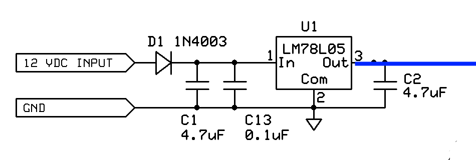
(above schematic has clickable areas that can be used for navigation)
Power Supply Bill of Materials
Detailed Bill of Materials
| Check | Designation | Component | Marking | Category | Orientation | Notes | Circuit |
|---|---|---|---|---|---|---|---|
| [____ ] | C01 | 4.7 uF 10% | 475 | Ceramic | Power Supply | ||
| [____ ] | C02 | 4.7 uF 10% | 475 | Ceramic | Power Supply | ||
| [____ ] | C13 | 0.1 uF | black stripe
 | SMT 1206 | SMT | Power Supply | |
| [____ ] | D1 | 1N4003 | 1N4003 | Axial | E-W | Power Supply | |
| [____ ] | gnd | shunt wire (cut-off lead) | misc | Power Supply | |||
| [____ ] | U1 | LM78L05 voltage regulator | LM78L05
 | TO-92 | Power Supply |
Power Supply Summary Build Notes
- Install SMT cap
- Install topside components
- Install ground test loop
- Test the Stage
Power Supply Detailed Build Notes
Bottom of the Board
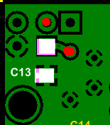
Install SMT cap
Install C13 SMT 0.1 uF cap
Take care to avoid solder "splashover" that could clog up the thru-holes above and to the right of C13 (see red dots in above graphic)
| Check | Designation | Component | Marking | Category | Orientation | Notes |
|---|---|---|---|---|---|---|
| [____ ] | C13 | 0.1 uF | black stripe
 | SMT 1206 | SMT |
Top of the Board
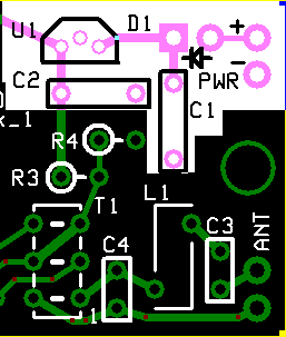
Install topside components
Install the two blue capacitors, U1, and D1. Install D1 such that the cathode end (the end with the band) is facing up and forms a hairpin. The hairpin lead will go into the square thru-hole (refer to the Completed Stage, Topside picture below).
| Check | Designation | Component | Marking | Category | Orientation | Notes |
|---|---|---|---|---|---|---|
| [____ ] | U1 | LM78L05 voltage regulator | LM78L05
 | TO-92 | Take ESD precautions | |
| [____ ] | D1 | 1N4003 | 1N4003 | Axial | E-W | |
| [____ ] | C01 | 4.7 uF 10% | 475 | Ceramic | ||
| [____ ] | C02 | 4.7 uF 10% | 475 | Ceramic |
Install ground test loop
Using a short length of cut-off resistor or capacitor lead, fashion a short wire loop and solder it to the "ground" hole, such that the loop is available on the topside to provide a ground point for tests.

| Check | Designation | Component | Marking | Category | Orientation | Notes |
|---|---|---|---|---|---|---|
| [____ ] | gnd | shunt wire (cut-off lead) | misc |
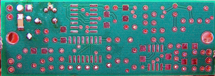
Power Supply Completed Stage
Top of the Board
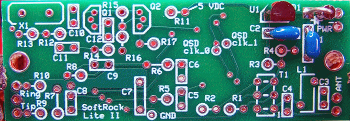
Bottom of the Board
Power Supply Testing
Visual Inspection
Test Setup
Using very good lighting and magnification, carefully inspect the solder joints to identify bridges, cold joints, or poor contacts.
Current Test
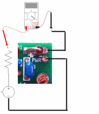
Test Setup
Test for current draw in 2 ways:
- Use a 12 volt power supply
- In one test there is also a 1k resistor in the series "chain" as well.
- in the second test, the setup is the same except that the current-limiting resistor is removed
Test Measurements
| Testpoint | Units | Nominal Value | Author's | Yours |
|---|---|---|---|---|
| With limiting resistor | mA | < 12 | 1.8 | _______ |
| Without limiting resistor | mA | 1 - 4 | 1.8 | _______ |
Voltage Test
Test Setup
Once the current draw test is successfully passed:
- Apply 12 Vdc (NO current limiting resistor) to the PWR + and - pads (upper right-hand corner of the board)
- Measure the voltage with respect to ground at the testpoints below

Test Measurements
| Testpoint | Units | Nominal Value | Author's | Yours |
|---|---|---|---|---|
| R11 hairpin (5 Vdc point) | Vdc | 5 | 4.93 | _______ |
| D1 cathode (square hole) | Vdc | 11-13 | 12.2 | _______ |