Introduction
This section assumes you are using the Rocky program for RX/TX functionality. In order to optimize the TX capabilities of the SDR, you need to balance the TX outputs of Rocky.
This process adjusts the phase and gain of each of the I and Q outputs of Rocky so as to eliminate the generation of image signals.
Equipment Requirements
| Designation | Value | Type | Orientation |
|---|---|---|---|
| 2nd RX | RX of Band being Calibrated | HF Radio w/S-Meter (or 2nd Softrock RX) |
Introductory Notes
Adjust I/Q balance in the transmitter
You must have a second receiver, e.g., your base radio, or another SoftRock, to perform TX balancing in Rocky. The second receiver must be able to indicate the strength of a received signal (e.g., S-Meter on radio or spectrum display on Softrock RX).
The TX Balancing routine in Rocky produces signals in the left and right channels of your soundcard, in two separate adjustment steps:
- The first step produces a "real" signal that is 24 kHz below the center frequency and an "image" signal that is s4 kHz above the center frequency. The user is then expected to adjust phase and gain controls so as to null the image (received on an external HF RX.)
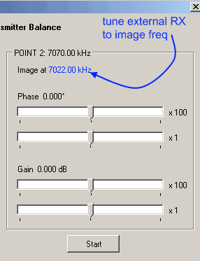
- The second step is a mirror of the first step, with the "real" signal being 24 kHz above the center frequency and the "image" bing 24 kHz below the center frequency.
Procedure
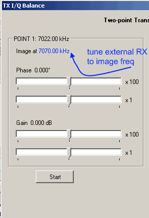
- Open the TX IQ Balance dialog (using center frequency of 7.046 MHz as example).
-

- Note the image frequency displayed on the left panel, and tune a second receiver
at that frequency. Disable AGC in the second receiver.
(If you do not hear the tone but the RX's S-Meter gives evidence of an signal, you are probably zero beating on the image frequency and need to adjust the RX's frequency up or down until you get the tone). - Press the start button on the left panel. The tone signal will be transmitted, and you should hear the image signal in the second receiver.
- Drag the Phase x 100 and Gain x 100 sliders very slowly, one tick at a time, and find such positions of those sliders that make the image tone in the second receiver decrease in amplitude.
- Once the x100 sliders are in their best positions, drag the x1 sliders, again very slowly, to further null the image tone. These sliders should make the image tone barely audible or even completely inaudible.
-

- Repeat steps 2 through 5 for the second calibration point (right panel)
Possible Problems
- If the I and Q signals are swapped, then the image and the main signal are also swapped. Make sure that the I/Q output signals are assigned to the Right/Left channels of the soundcard in the same way as the I/Q input signals, and that the Channels setting in the Settings dialog matches your channel assignment.
- If one of the I/Q output signals is missing, or there is a short circuit between them, QSE balancing is not possible. Fix the hardware problem and repeat the balancing procedure.
- If the receiver is permanently enabled (even while the board is in the TX mode), you will see the main signal and the image on the band scope. Unfortunately, this display cannot be used for image nulling. The balance settings that minimize the image spike on the bandscope are different from those that minimize the image in the transmitted signal, because the TX output signal enters the receiver through several different paths, not just through the antenna connector.