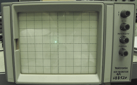
I had a report from Bob that R280 on his 620 was also fried. One more tidbit from Bob::
I found my C140, the 2.2uf cap at the rectifiers, had developed higher esr due to time and age I guess. I replaced it and the power being dissipated by R280 dropped to a more manageable 1/4 watt. The original 1/4 watt resistor was still underrated, but it would have lasted awhile I guess if the cap hadn't become sickly.
Bob
This might be a great spot to start. There seems to have been a design flaw there.
Additional repair information from Bernice:
Hello Leonard,
Turns out there was enough information and tek documentation for me to get that tek 620 monitor working.
Problem turns out to be in the -70volt supply, but a variation on what happened to your 620. This one had a rather messy previous failure of Q280 and Q285. It appears they shorted then cooked R287 (10 ohm) which burnt that area of the board. It appears both diodes CR139 & CR140 were also replaced when all that occurred.
This time, the -70V measured -44Volts or so with a LOT of switching supply raw AC bleeding into the -75V unreg supply. Both CR139 & CR140 died again along with C140 (2.2uF @200VDC_lytic). Turns out that 2.2uF was more high value resistor than capacitor. Replacing those parts got this 620 back up and running.
The on going failure of CR139 & CR140 appears to be due to tek's choice of using insufficient diodes for this application. These diodes need to have enough break down voltage (no less than 400V) and fast transient recovery time. If the trr is too slow, the diodes heat up internally from the switching loss and die a slow death. They are also subject to inductive voltage spikes that can cause break down damage to the junctions. These diodes should be replaced with a modern high voltage, fast trr diode that are now common in switching power supplies like the UF4004-4007. Beyond this problem, the 2.2 uF capacitor in the voltage doubler is subject to HF ripple currents and it needs to be a low ESR 'lytic designed for switching power supplies, or similar film or ceramic capacitor. When this cap fails, the results can be messy.
Parts used to repair this 620 were:
*Two, UF4007 fast recovery diodes.
*One 2.2uF @ 200VAC, low ESR polyester film capacitor.
*Two 2.2uF @ 200VDC low ESR 'lytic capacitors that were associated with the -70V supply (precautionary measure)
*One 5,000uF @ 35VDC snap in capacitor to replace the Mallory can capacitor that has dried out resulting in making the regulators work harder than they should. This got rid of the 60 Hz trace bounce.
Thanks for posting this on the tek 620's power supply as bit of info got this 620 monitor working and out of the scrap pile. If you like, share this bit of info about why the -70V supply fails in these tek 620 monitors.
I acquired a Tektronix 620 XYZ monitor off of ebay to use as a display for a Tektronix 7612D Programmable Digitizer. The ebay add had a picture showing a dot in the middle of the screen which is what you'd expect with no X or Y input. That demonstrated that at least it had high voltage and the CRT probably was good.
Upon receiving it, I found that the intensity control would not turn the display up or down and the position controls would only move the dot about 1 division in any direction.

Time for a repair job. Searching the internet for documentation, I was unable to find any for much less than $100. Kind of expensive to repair a $40.00 acquisition. After posting a plea for help on the yahoo Tektronix forum, I received an email from Dave at Artek Media. He had access to a manual and would scan it for me for a very reasonable $12.50. I was now on the way to begin the repair.
After opening it up, I made a few basic power supply measurements and found that the -70 volt power supply was 0. This made sense as that supply was used in both of the deflection amplifiers and the intensity circuit. Backing up further on the schematic, I arrived at the transformer.
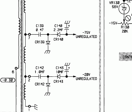
There was no -75 but at the transformer pin 7, there was a 100 volt pk-pk sine wave. At least the transformer is good. This circuit is a pretty standard voltage doubler so after a quick look with the scope, the anode of CR139 showed an AC sine wave, it was time to check the diodes. An ohmmeter check displayed the common 10-1 front to back ratio but it was 4 megohm forward and 40 meg ohm reverse. I think I'll change them.
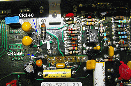
Luckily I was able to change the diodes without having to remove the circuit board. That looked like a pretty involved process. I replaced them with 2 1N4007's and powered it up again expecting smoke, a bang, or a flash. It was pretty disappointing as nothing bad happened and all of the smoke stayed inside where it belonged. I now had -83 volts out of the doubler. A quick look at the display showed no change in operation. There must be more problems. Checking the -70 volt line now displayed -3 volts. At least that was in the right direction. On to the -70 regulator circuit.
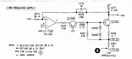
The way this circuit works is the output of the -70 regulator is fed through a 2 resistor series network back to the +15 volt supply with the tap point of the resistor string fed into a op amp.The op amp is going to output whatever it takes, (within it's limitations), to make pin 5 the same voltage as pin 6, in this case, 0 volts. That means that 15 volts will be dropped across R274. Ohm's law says that will produce 498.339 ua's of current through R274. An ideal op amp has infinite input resistance so we will assume that no current flows in or out of pin 5. This means that our 498.339 ua's also flows through R276 towards pin 5. I like electron flow. This drops 69.76 volts across R276. The left side is 0 volts so that makes the right side -69.76 volts. Pretty close to our -70 volts.
As the -70 volts goes more positive, pin 5 goes more positive and since that is the non-inverting input, the op amp output goes more positive and forward biases Q280 on more causing it to conduct more. Q280 pulls it's current from the -75 unregulated through R287, R281, and R280. As the current flow through R281 increases, it's voltage drop increases, increasing the forward bias on Q285 which causes it's resistance collector-emitter to decrease causing it's collector to go more negative. This negative increase is fed back through R276 causing the voltage at pin 5 to try to go negative but the op amp wants 0 volts there so it decreases it output voltage on pin 7 decreasing the conduction of both Q280 and Q285.
Now that we know how it's supposed to work, lets look at the non-working symptoms.
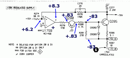
We can see all kinds of problems here:
The voltage at pin 5 should be 0
Q280 is either turned on hard or shorted
There is no voltage drop across R281 which produces no forward bias for Q285 so it is turned off resulting in the no -70 condition.
If Q285 was open, there would be no - voltage output but there should still be a voltage drop across R281. That is telling me that there appears to be no current flow through R281 but the voltage drop across R280 says there should be 17.66 ma's of current through it. 17.66 ma's through R281 should drop 4.76 volts. Something here is contradictory. These 2 measurements don't go together. Time to ohm out the 2 resistors. R281 measured about 270 ohms in circuit. For it to have been bad and cause the symptoms, it would have had to been a short, which would have given us the 0 volt drop. R280 measured very high in circuit. After removing it, I found it was open. Under close visual inspection, you could actually see that it was defective.
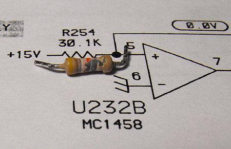
After replacing it, the 620 now functions correctly.
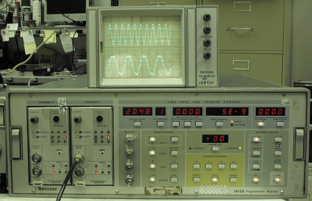
The final test. Running it with the digitizer. Now that I have a good display, I can try to learn how to use it.