Miscellaneous Circuits
In this section we will add the simple circuits. We haven't needed them to this point but from now on, it will be easier to test the board with them completed.
To simplify the process, we will now install all of the remaining chip capacitors on the bottom of the board, then we will build and test the PTT circuit.
The PTT circuit requires the following components.
| R35, R36 | 10k ohm | resistor bag | |
| R33 | 2.21k ohm | resistor bag | |
| R34 | 4.99k ohm | resistor bag | |
| C36 | 0.033ufd | capacitor bag | |
| D3 | 1N4003 | transistor bag | |
| Q9 | 2N3904 | transistor bag | |
| Q10 | 2N3906 | transistor bag |
Install the components.
We can now test the circuits we just installed. To test the PTT circuit, connect your voltmeter to the Switched 12 volt output point, apply +5 or +12volts to the PTT INPUT point. This will turn Q9 on applying a ground to the bottom of R34 and creating a path for current flow through R33. Current flow through R33 will create a voltage drop across it and turn on transistor Q10 passing +12 volts to the switched 12 volt line.
Connect the meter + lead to the S12v test point, (the green clip) , and apply +5 or +12 volts to the PTT test point, the black clip). Be careful as the second hole up is ground! Massive amounts of current may flow if you apply 12 volts there!
| R40, R43 | 22.1k ohm | resistor bag | |
| R41 | 10k ohm | resistor bag | |
| R42 | 221 ohm | resistor bag | |
| Q11, Q12 | 2N3904 | transistor bag |
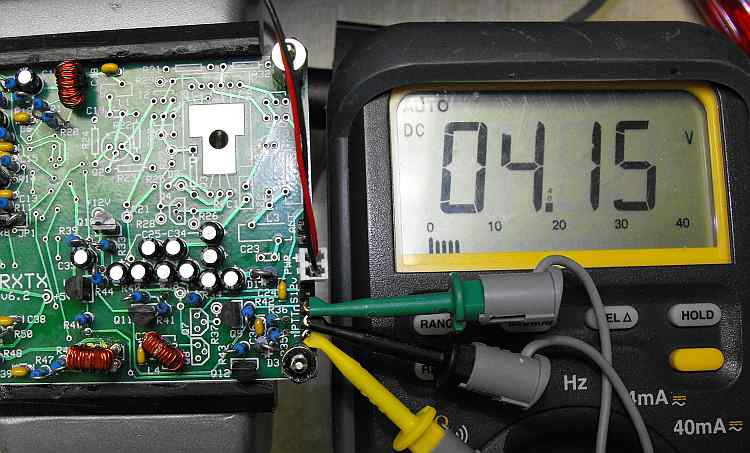
To test this circuit, connect your voltmeter +to the /PTT OUT point. This is the 3rd pad up from the lower right corner of the board. It is marked 0 on the board. Connect the voltmeter - to ground. A good spot to do this is the 2nd pad up or the power supply lead. You should read a little over 4 volts.
Apply +5 or +12 volts to the PTT INPUT point. The voltage should go to about 0. Move your voltmeter probe to the hairpin of R45. You should read about +5 volts. Remove the PTT voltage and the meter should drop to about 0.
We will add the low pass filter with the antenna switching circuit. This will require us to wind 2 more torroids. Take two 37-2 red cores and we will wind 19 turns of #26 wire on them.
We installed C24 earlier when we were testing the receiver mixer.
| R37, R38 | 4.99k ohm | resistor bag | |
| C21, C23 | 470pfd | capacitor bag | |
| C22 | 820pfd | capacitor bag | |
| Q7, Q8 | BS170 | IC bag | |
| L2, L3 | T37-2 core | 1.4uh |
We can test the filter installation now. Connect a generator to the antenna input and your scope to either the tip or ring connector.

I'm inputting 3.536mhz and getting out 7.996khz at about 80mv's
Select the following components for the audio out amplifier.
| R1 | 22.1 ohm | resistor bag | |
| R2 | 1k ohm | resistor bag | |
| C1 | 10 ufd | capacitor bag | |
| Q1 | BS170 | IC bag |
Install the 4 components.