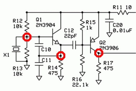
After building my softrock, I connected it to a signal generator and powered it up. It didn't seem to be working so I went into the troubleshooting mode and below is the process I went through:
We will start at the oscillator first. The testpoints are marked on the schematic.

0 volt reference is the bottom of the scope display on all pictures unless stated differently. 10x probe used. All readout amplitudes are actual voltage. We have a 4.8 volt sinewave that goes from 0 volts to +4.8 volts.
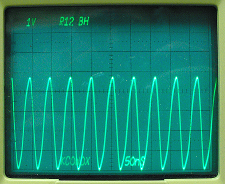
Q1 base signal taken at the buttonhook of R12. The dc voltage level is the middle of the sine wave and is about 2.5 volts. Thats being produced by the series resistor string of R12 and R13. Calculation shows that the 2.5 volts is correct.
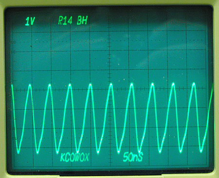
Q1 emitter signal taken at buttonhook of R14.
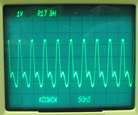
Q2 emitter signal at the buttonhook of R17.
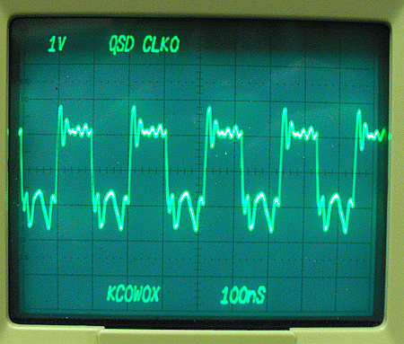
This looks like a bad QSD Clk0. The low part of the square wave should go down to 0 volts and it is only dropping to around 2.5 volts. To isolate the dividers, I lifted pins 14 and 2 on the mixer with no change in the clock voltages. Testing all other output waveforms on U2 displayed that they also were a square wave between 2.5 volts and 5 volts. Time to change U2..
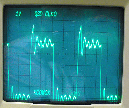
U2 has been changed and the QSD CLK 0 is a 5 volt square wave as expected.
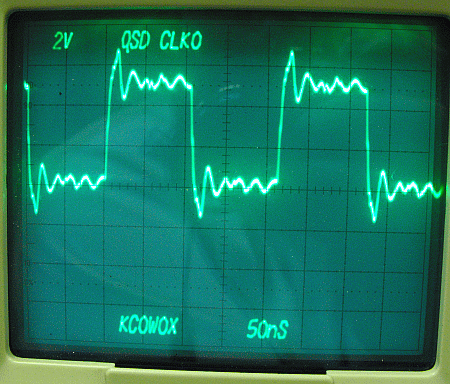
Here the DC reference has been moved up and the volts/division has been changed to allow inspection of the waveform.
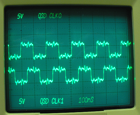
The 2 clock signals are 90 degrees out of phase as required.