Frequency Counter
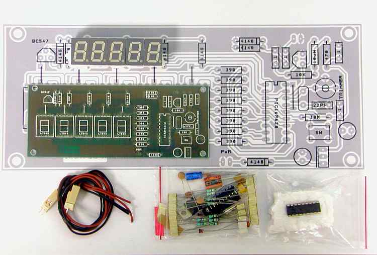
Your frequency counter kit contents should look like this.
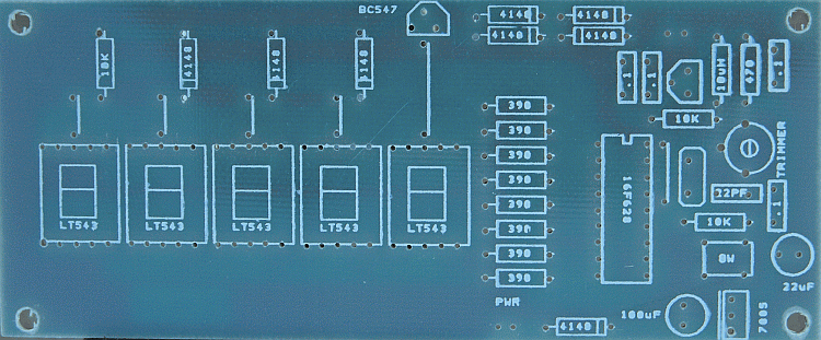
The received board looks like this.
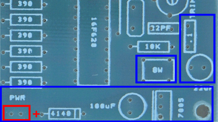
At this point, you need to make a decision on how you want to use the counter. If you plan on putting it in a case, you will need to assemble some of the parts on the back of the board as they will stick up past the face of the displays. The documentation will assemble for a case installation.
Power Supply Section
We will need the following components.
1 |
1N4148 | diode | |||
1 |
0.1uf | capacitor | 104 | ||
1 |
47uf | capacitor | |||
1 |
220uf | capacitor | |||
1 |
7805 | regulator | |||
1 |
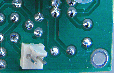
power connector | back of board | |||
1 |
switch |
Install the marked components using the diagram below. The connector, 7805, 2 electrolytic capacitors, and the switch will be mounted on the back of the board. It will be easier to install the switch first then the 7805.You may need to enlarge the holes slightly for the power connector. A #60 drill works well. The electrolytic capacitor values may vary some from the values silk screened on the board. Observe polarity when installing the capacitors. The metal tab of the 7805 should be to the right as shown in the picture. Mount the power connector oriented so that the black wire goes to ground. The connectors may be soldered by heating the pin on the top of the board and applying solder through the small opening in the body of the connector near the outside edge of the board.
The completed back should look like this:
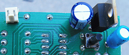
After assembly, apply +12 volts to the brown wire and ground to the black wire. Verify 5 volts on the bottom lead of the 7805.
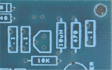
Amplifier Section
3 |
0.1mf | capacitors | 104 | |
1 |
10uh | inductor | brn-blk-blk | |
1 |
470 | resistor | yel-vio-brn | |
1 |
10k | resistor | brn-blk-org | |
1 |
c547b | transistor | ||
1 |
input connector |
Note:
After constructing mine, I noticed the low level of voltage at the collector of the amplifier transistor. In reading the DL4YHF literature that came with the kit, I noticed that he called for a 27k and said that it could be adjusted to change the voltage drop across the collector resistor. I placed a resistor sub box in the circuit and increased the value of the 10k. It seems to be optimal around 47k-56k. I replaced the original 10k with a 47k and the counter works great up to 30mhz. With adjustment of the resistor and the inout voltage, the counter worked great to a little over 50mhz. For a bitx digital dial, 47k-56k should be good.
Install all of the components using the diagram below. The frequency input connector will be installed on the back of the board
The back of the board should look like this.
Apply 12 volts to the power connection and check the voltages on the transistor.
| collector | 1.045 | |
| base | .704 | |
| emitter | 0 |
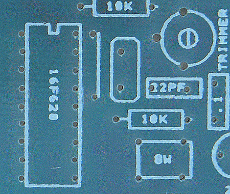
PIC Section
1 |
22pf | capacitor | 22 | |
1 |
0.1uf | capacitor | 104 | |
1 |
10k | resistor | brn-blk-org | |
1 |
trimmer | capacitor | brn-blk-org | |
1 |
IC socket | |||
1 |
crystal | 20.000 | ||
1 |
jumper |
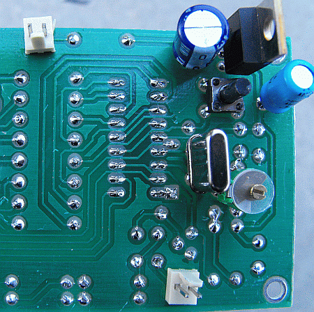
Install all of the components using the diagram below. The crystal and the trimmer will be mounted on the back of the board. Use the socket for the PIC and install a jumper just to the right of it.
The back of the board is now complete and should look like this.
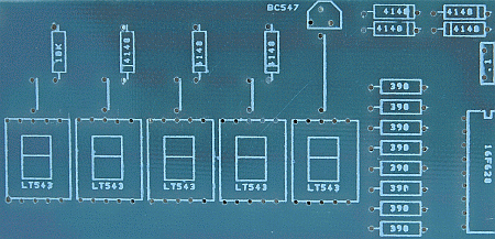
Display Section
We will need the following components.
8 |
390 ohm | resistor | org-wht-brn | |
1 |
10k | resistor | brn-blk-org | |
7 |
1n4148 | diodes | ||
1 |
transistor | |||
5 |
displays | |||
5 |
jumper |
Install all components observing polarity on the diodes. Install the displays last. Verify that all of the display leads are through the board before soldering the displays. It will be hard to remove them if one of the leads are bent over on top of the board.
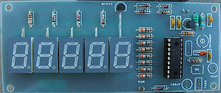
Completed Board
The completed board should look like this.
Calibration
Apply power to the board and connect a known frequency signal source to the input frequency connector. Set the amplitude to around 0.5 volts. Adjust the trimmer until the frequency displayed is correct. If the frequency readout is too low and can not be adjusted high enough, you may need to change the 22pf capacitor. I changed mine to 47pf. Be sure to use an npo capacitor.
The counter auto-ranges to display as many digits as it can. If the input amplitude is too low, the second digit from the right will display "0" and the rest will be blanked.