Bitx Version 3 Linear Amplifier Assembly
The power supply section has 2 options.
1 - AC input and a higher voltage on the IRF510 and +12 volts to the bitx.
2 - +12 volts applied to both the final and the exciter.
Power Supply - High voltage on the final
We will need the following components.
|
2 |
0.1uf | capacitors | ||
|
1 |
1.0uf | capacitor | ||
|
2 |
2,200uf | capacitors | 25 volt | |
|
1 |
100 ohm | resistor | ||
|
1 |
1k | resistor | ||
|
4 |
1n4001 | diodes | ||
|
1 |
LM317 | voltage regulator | ||
|
1 |
relay |
see below |
||
|
8 |
header pins |
Relays may be purchased from:
Omron G5LE-14-12 (Newark)
http://newark.com/omron-electronic-components/g5le-14-dc12/power-relay/dp/36K1937?_requestid=36176\
or
677-SRUDH-SH-112D1
(Mouser)
http://mouser.com/Search/Refine.aspx?Keyword=677-SRUDH-SH-112D1
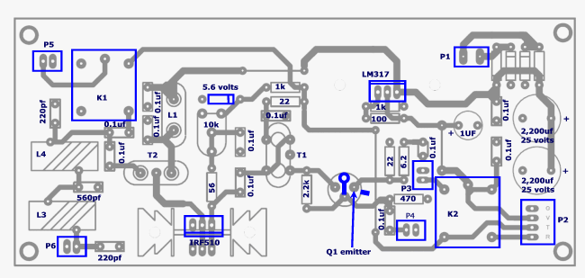
Install components as shown below observing polarity on the diodes and electrolytic capacitors.
The original layout drawings for the linear show a 980 ohm resistor in the voltage determining network for the LM317. Using a 1000 ohm resistor will result in a regulated voltage of around 13 volts for the exciter board and is perfectly acceptable.
Testing the AC power supply
Do not apply more than 16 vac to the ac supply or the working voltage on the 25 volt electrolytic capacitors will be exceeded!
Apply the ac power to P1. Measure the voltage between P2 - V and G. Using the resistance values listed it should measure approximately 13 volts.
|
volts |
Measure the voltage at the right side of the LM317. This will vary depending on the AC input voltage. It should be more than 16 and less than 25.
|
volts |
You can test the operation of the relay by connecting the voltmeter to P2 - T and shorting the 2 pins of P3 This is the PTT switch point. When the relay operates you should read the 12 volt supply.
Power Supply - Using 12 volt battery power
When
using a 12 volt battery supply we do not need the LM317. The +12 volts is
applied to both the final and the exciter board.
We will need the following components.
|
2 |
0.1uf | capacitors | ||
|
1 |
1.0uf | capacitor | ||
|
2 |
2,200uf | capacitors | 25 volt | |
|
1 |
1n4001 | diode | ||
|
1 |
relay | furnished with board | ||
|
8 |
header pins |
Relays may be purchased from:
Omron G5LE-14-12 (Newark)
http://newark.com/omron-electronic-components/g5le-14-dc12/power-relay/dp/36K1937?_requestid=36176\
or
677-SRUDH-SH-112D1
(Mouser)
http://mouser.com/Search/Refine.aspx?Keyword=677-SRUDH-SH-112D1
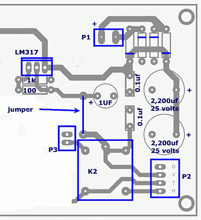
Install the components as shown below. Be sure to install the jumpers.

Testing the 12 volt power supply
Apply DC power to P1 observing polarity. Measure the voltage between P2 - V and G. It should measure the DC supply voltage.
|
volts |
You can test the operation of the relay by connecting the voltmeter to P2 - T and shorting the 2 pins of P3 This is the PTT switch point. When the relay operates you should read the 12 volt supply.
Driver
We will need the following components. We will install components for the final input circuit so we can test the driver circuit under load.
|
5 |
0.1uf | capacitors | ||
|
1 |
6.2 ohm | resistor | ||
|
2 |
22 ohm | resistors | ||
|
1 |
56 ohm | resistor | ||
|
1 |
470 ohm | resistor | ||
|
1 |
1k | resistor | ||
|
1 |
2,2k | resistor | ||
|
1 |
10k | potentiometer | ||
|
1 |
5.6 volt | zener diode | ||
|
1 |
2n2218 | transistor | ||
|
1 |
transformer | 8 bifilar turns on FT37-43 core | T1 | |
|
2 |
header pins | P4 |
Transformer, T1, will take 7" wire. #26 - #30 is fine. With the specified core, the inductance should be around 22uh although it really isn't particularly critical. See http://golddredgervideo.com/kc0wox/bitx/transformers.htm for a discussion why.
Install T1 as shown below. If you don't have colored wire, verify with an ohm meter that the are connected as shown. After removing the insulation, tin the leads and twist the red and green wire together to form the center tap portion of the transformer.

Install components as shown below. Board pattern for Q1 may vary slightly from drawing.
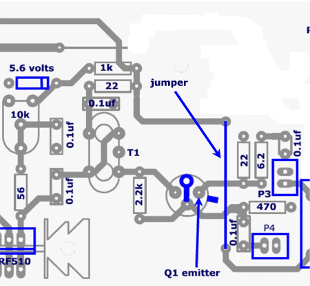
Q1 should look like this after installation. Note the direction of the emitter tab.
Apply power to the input connector. Short the 2 pins on the PTT
connector, P3, to switch to transmit mode and
measure Q1 voltages. Compare
them to the chart below.
| Q1 | ||
| Collector | 11.88 | |
| Base | 1.90 | |
| Emitter | 1.188 | |
Connect the digital voltmeter to the bottom end of the 56 ohm resistor. Adjust the pot and verify that the voltage varies between 0 and the zener's voltage rating. After verification, adjust it fully CCW for a reading of 0 volts. This is the preliminary bias setting of the IRF510.
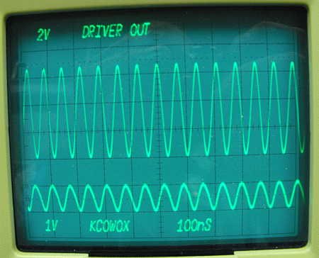
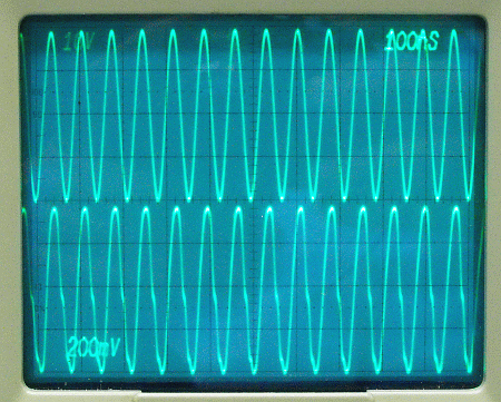
With an input signal at P4 of 14.250mhz and an amplitude of 1 volt pk-pk, the signal voltage at the lower end of the 56 ohm resistor should be around 6 volts pk-pk as shown below.
This completes the driver section.
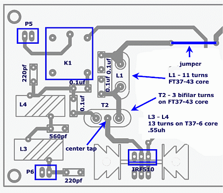
Final
We will need the following components.
|
4 |
0.1uf | capacitors | ||
|
2 |
220pf | capacitors | npo | |
|
1 |
560pf | capacitor | npo | |
|
1 |
rfc | 11 turns #28 FT37-43 | L1 | |
|
2 |
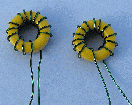
inductor | 12 turns #28 T50-6 .55uh | L3, L4 | |
|
1 |
transformer | 3 bifilar turns #28 FT37-43 | T2 | |
|
1 |
IRF510 | FET | ||
|
1 |
relay |
furnished or see below |
K1 | |
|
4 |
header pins | P5, P6 |
Relays may be purchased from:
Omron G5LE-14-12 (Newark)
http://newark.com/omron-electronic-components/g5le-14-dc12/power-relay/dp/36K1937?_requestid=36176\
or
677-SRUDH-SH-112D1
(Mouser)
http://mouser.com/Search/Refine.aspx?Keyword=677-SRUDH-SH-112D1
L1 will take 8" of wire and should measure around 42uh.
The actual value
isn't too critical as this is used as a radio frequency choke and as long as it
has plenty of inductance, value really doesn't matter. Mine measured 36.67uh.
When using cores with a high Al, the calculated vs. actual will vary
more.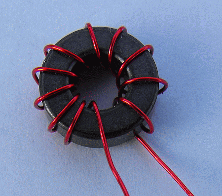
L3 and
L4 will take 8" of wire and should measure .55uh.
Wind 13 turns on a T37-6
core. Be sure
to spread out the turns over the whole core. If they bunch together, it will
raise the inductance.
T2 will take 4" of wire and each winding should measure
3.15uh.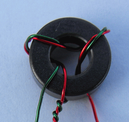
Install all of the components but the jumper, the relay and the IRF510. Do them last. This will give you a little more finger room. The jumper will be left off as this is the current meter point to set the bias on the IRF510.
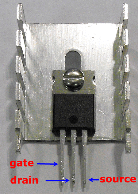
The IRF510 pin out is shown below.
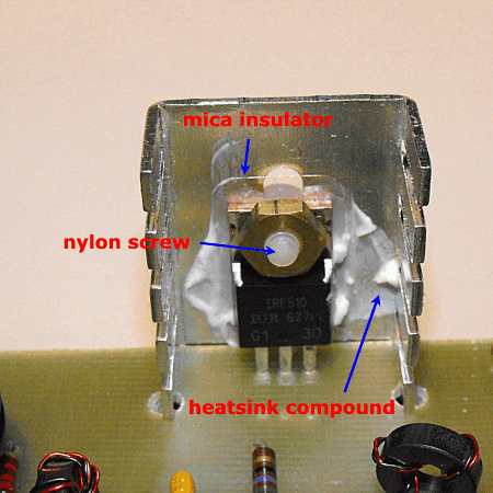
Use some heat sink compound between the FET and the heat sink.
The completed installation should look like this. Using a brass nut is an option. The nylon screw isn't. The heat sink needs to be insulated from the FET's tab. Use an ohmmeter to verify it both before and after installation on the board. If your heat sink is not aluminum, you can scrape the solder mask off around the tabs on the back of the board and then carefully bend the tabs over. Do this before you solder the IRF510 leads. Using a heavy soldering iron, solder the tabs to the ground plane of the board. This will ground the heat sink.
Testing
The following tests were done using a 28 volt power supply connected to the diode bredge input pins at P1.
Connect a dummy load to P6.
Connect a ma meter in the place of the jumper not installed when construction the final. The + lead should be to the right towards P1. Set the meter to measure 50 ma's.
Verify that the final bias pot is fully CCW.
Apply power. You should read 0 current as the FET has not been biased on yet. If you do, turn off power and verify that the heat sink is not grounded and that the FET drain is not grounded.
Adjust the bias pot for 40 - 50 ma's current. This will probably be a little over halfway on the pot. It will come on fast so adjust carefully.
If you have an oscilloscope, connect it across the dummy load.
Apply a signal to P4 and monitor the output. It will take around 1 volt pk-pk to get 4 watts out. Do not leave the amp on for more than a short time without using a fan to cool the heat sink.
800mv's in from signal generator and 4 watts out. Distortion is loading of the generator by the linear.
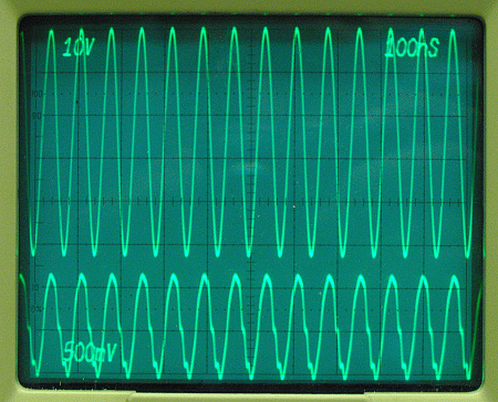
7 watts out with 1.3 volts input.
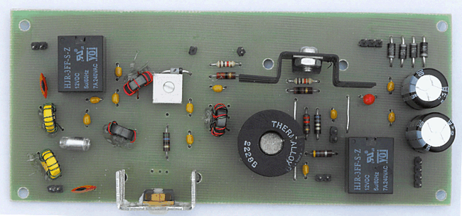
The completed board. The toroids have been glued to the board using a hot glue gun. The final bias jumper is not shown in place.
Board Interconnects
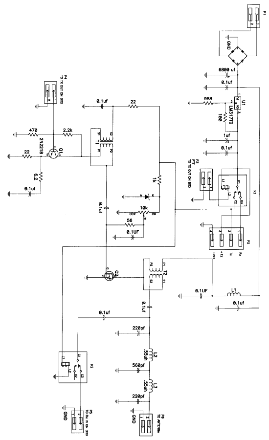
The antenna switching is handled by the linear board. Print out
http://golddredgervideo.com/kc0wox/bitxver3new/bitxlinearrotated.gif to get a horizontal version of the linear schematic and connect the boards together as follows:
Linear connections
P6 connects to the antenna
P5 on linear connects to RX Ant on the exciter board.
P4 connects to To Pa on the exciter board.
P2
Rx connects to R on Power Connector on exciter board
Tx connects to T on Power Connector on exciter board
+12 connects to V on Power Connector on exciter board
Gnd connects to G on Power Connector on exciter board
P1 connects to +12 volt power.