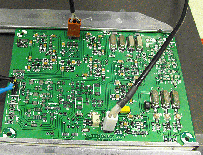
The board is setup as shown
The input is the brown connector and is plugged into MX1 pins 2 and ground. T1-1 is not in circuit. This shouldn't be a problem as the IF amplifier should isolate any change in input signal impedance from the filter.
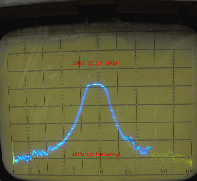
I used 100pf for C14 and C16 with C15 200pf and .1uf for C2 and C10. This is only about 1.2k wide so is too narrow. The BITX20a kit filter used 100pf for the input and output coupling caps and 82pf and 100pf for the filter capacitors. Most of the ones I have tested run a little wide.
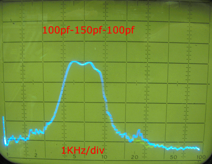
Decreasing the middle capacitor from 200pf to 150pf widens it out but takes a toll on the top of the waveform.
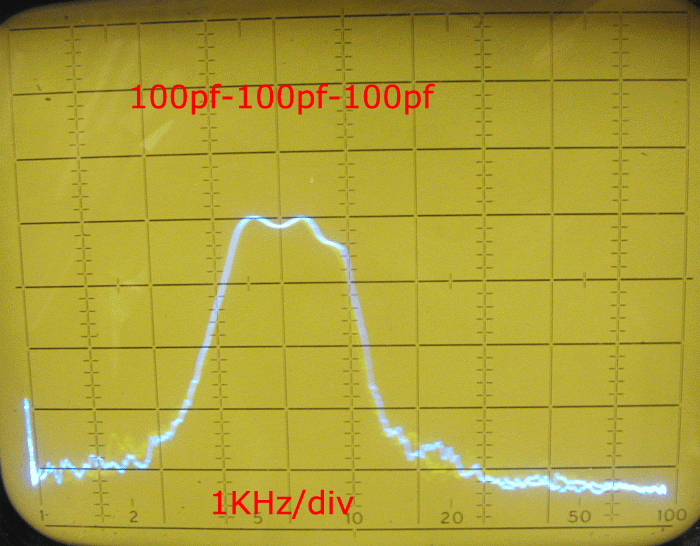
Changing it to 100pf almost has the bandwidth usable.
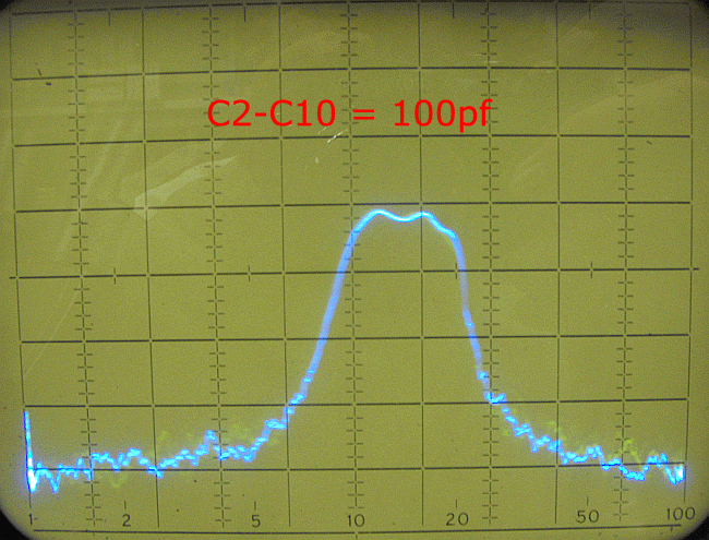
C2 and C10 have been changed to 100pf instead of 0.1uf. There seems to be very little change so I'll change back to the original 0.1uf.
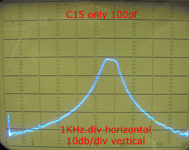
So far, everything has been too narrow. Time to make some major changes. Lowering the value of capacitors is supposed to widen the bandwidth so off with all of the capacitors and put in a 100pf capacitor for C15. Lets look at it with C15 only in circuit as C14 and C16 are out.
Still narrow. I didn't have any 82pf capacitors so in with what I had. 68pf for C14 and C16

Now that's a little more like it! A little bumpy but it definitely looks usable. This may be as good as you get without doing any crystal matching.
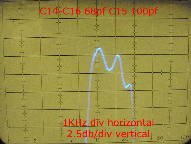
Expanding the vertical display to 2.5 db/division, it looks like we have about 5db of variation. Not great but looking at it this way shows every little imperfection.
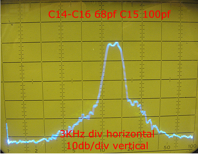
Changing the display to 3KHz/div horizontally makes it look a little better. I will stick with this until I get time to match crystals and then I'll add to this after using a matched set.