These voltages are what I would call "minimum". If you have more, it's probably good. With these voltages I was able to adjust the drive to get more than 12 watts out.
Unless otherwise noted, there is a 2 KHz, 50 millivolt signal applied to the mike input connector. If you have R92 on the board for electret mike voltage, be sure and capacitor couple the input signal. Something around 1-10 ufd should be great.
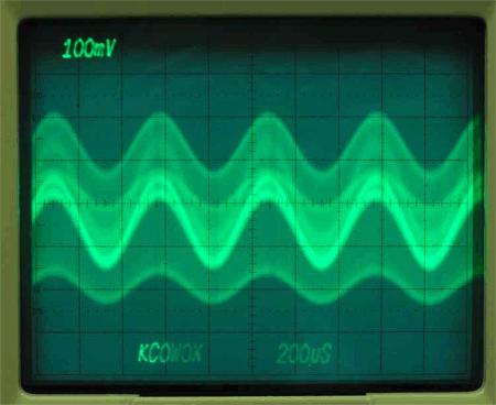
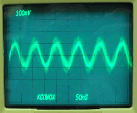
This signal is at the buttonhook of R77. R66 pot is fully CW or CCW. What you are seeing is the 11 MHz BFO coupled back through T6 being varied at the 2 KHz rate. This is not modulated at this point. The 2 signals have just been linearly added. For modulation to occur and new frequencies be produced, the signal has to travel through a non-linear device. This will be the diodes, D14 and D15. We will have a modulated waveform, double sideband, after modulation through the diodes at R66.
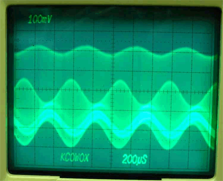
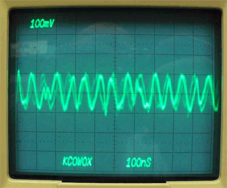
This signal is at the buttonhook of R77. This signal is with R66 turned the opposite way. The 2 extremes may not give you the same voltage.
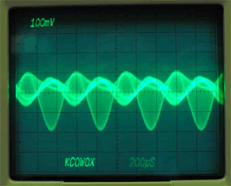
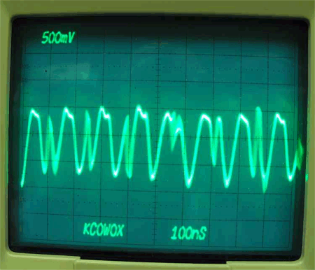
Buttonhook of D13 with R66 at one end. There are 3 frequencies present here. The BFO, the upper and lower sideband.
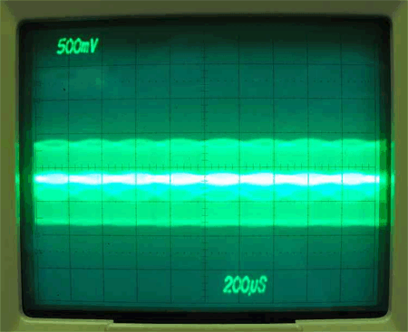
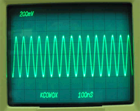
Buttonhook of D13 with R66 balanced. There are now only 2 frequencies here. The lower and the upper sideband. Balancing R66 has removed the carrier frequency.
Buttonhook of D11. The crystal filter has removed the lower sideband. This is now basically only one frequency. The "fuzz" is caused by extra high frequency components and harmonics. This will all be removed later by the band pass filter.
This is the junction of R14 - L10. After mixing the upper sideband with the VFO frequency, we are now at 14 MHz. Adjusting the VFO should change the frequency.
This is the buttonhook of D2. The signal frequencies here are the VFO + the upper sideband, the VFO - the upper sideband and all of their sums and differences. The band pass filter's job is to get rid of everything but the upper sideband frequency. If you don't have at least this much signal voltage, you probably won't be able to get enough drive. The band pass filter has a 5db loss. 6db is 1/2 voltage and we want to end up with around 800mv's after the filter.
This is the junction C11-C13. The band pass filter has removed all of the extraneous frequencies and left only the upper sideband frequency. This should be a clean looking sine wave. The adjustment of C14 and C18 in the band pass filter will have a great effect on the signal level. You want to adjust them at the frequency area that you plan on using the most. The scope probe will be de tuning the basdpass filter while connected to this point. The final tuning of C14 and C18 should be done with the scope connected either at the junction of Q20-R83 or at the dummy load after adjusting the PA bias.

This is the junction R83 - Q20. With the scope probe out of the filter, readjust C14 and C18. With this much drive voltage, you should be able to drive the PA to 10 - 12 watts output with the drive pot less than 3/4th's full CW. The adjustment of the PA bias is very sensitive and if you are unable to get full power out, reset and readjust.