Bitx Kit Section Signals
While troubleshooting bitx kits, I usually ask myself the question, "Is this signal correct?" To help in the future I began keeping notes. This page is documentation of the process of tracking the signal level changes while moving from block to block in my transceiver. No absolute signal levels are given because of the way I have to make the measurements. They are relative levels to one another. The main reason is you can't just probe around with the spectrum analyzer because it has a 50 ohm input impedance and you would drastically change the circuits impedances.
Lets start after we generate the sideband signals with T6.
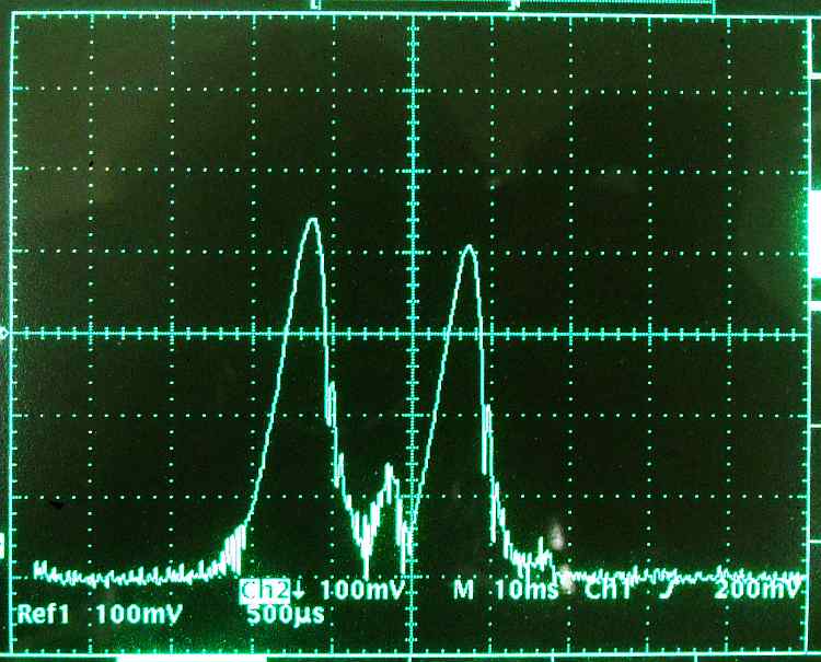
This is at the buttonhook of D13. We have generated a double sideband signal using T6 with an 11 MHz input from the BFO and a 2khz audio signal from the mike amplifier. What we see here is the carrier as the little hump just to the left of the center. The 2 large signals are the upper and lower sideband. The horizontal display is 2 KHz/division and the vertical display is 10db/division. I am guessing the the difference in the 2 sidebands is due to a slight loading of the upper sideband by the crystal filter. We are seeing a carrier rejection of about -25db.
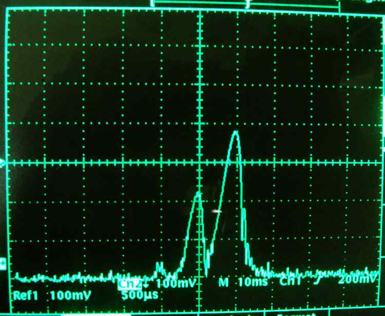
This is at the buttonhook of D10, the output of the crystal filter. If you compare the before and after pictures you will see that there was about a 3db loss going through the filter. The carrier is on the center graticule mark. It's quite likely that it's rejection could be improved by adjusting R66 and C65 but it wasn't particularly important for this series of pictures. The important signal is the upper sideband.

We are connected to the buttonhook of D11. We only show a 12db gain for the stage. The schematic calls for an 18db gain. This bears investigating, especially since the drive voltage out is about 1/2 of the voltage it should be. 1/2 voltage is -6db.
Since the receiver and transmitter circuit stages are identical, lets test the receiver amplifier.
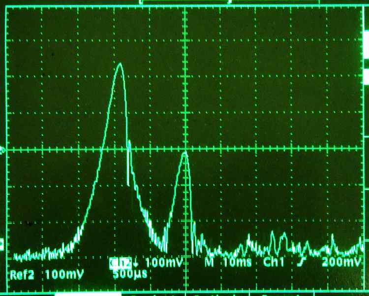
We are injecting a signal into the antenna, receiving it, and looking at it at D11's buttonhook. The large signal on the left is the BFO. Our injected signal is the one on the center graticule It is about 1/2 small division below the center line. Each small division is -2db so we are about -1db below the center.
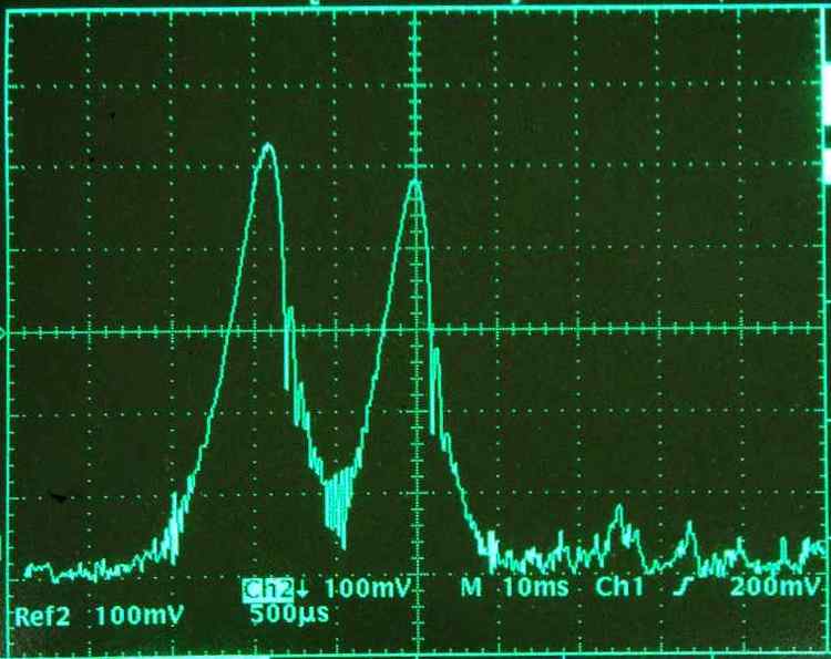
This is the output of the amplifier stage at D10's buttonhook. This shows +18db gain above the center line and we started at -1db below the center line. It looks like the receive amplifier has +19db of measured gain. It's time to examine the transmitter amplifier closely.