We are going to inject a far larger signal than normal into the antenna connector. This will make following the signal along easier and really doesn't overdrive the circuits until we get to the audio stages. The other change we will make is to use a x1 scope probe to better see the small signal levels. If you use a x10 probe, the signal levels in the pictures may not match well. I didn't test the theory to find out.
Here's our input signal. 30 millivolts pk-pk at 14.250 MHz. Apply this to the antenna connector.

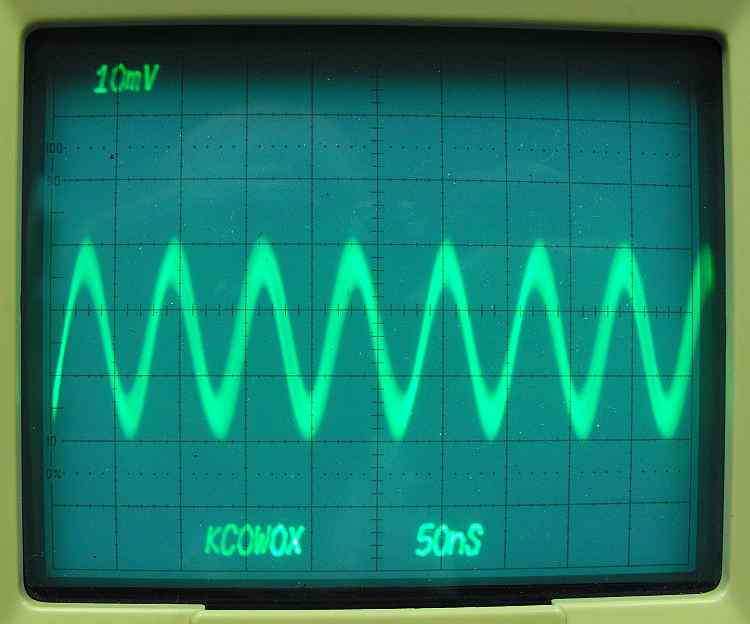
This is looking at the buttonhook of D2. We started at the antenna with 30mv and now we have 15 mv. 1/2 voltage is -6db. If you look at the schematic directly above C24 you see the caption "RX: 6 db total loss". We have just checked out all of the low pass filter, the rx switching, and the band pass filter. If you have excessive loss, check the signal at C11. This would isolate the problem and tell you which way to look.
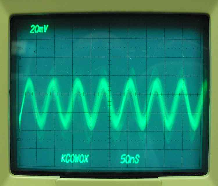
We are at the buttonhook of D3. We have a little less than 60 mv's here. If we use the formula db=20log E1/E2 we have 20 log 60/15.
or 20 x .602 or 12.04 db gain. The schematic shows 8.5 db of gain for the circuit so we are fine. Why do we have more gain? Measuring the signal levels with the amount of noise present on the signal makes the precise amplitude of the signals hard to decipher.
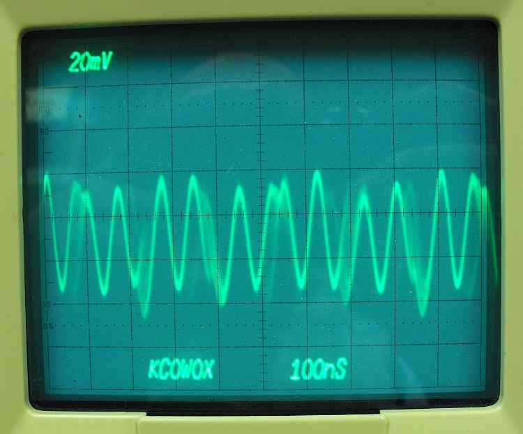
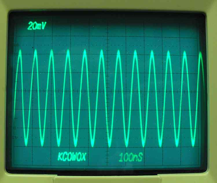
We are at the buttonhook of D11. Notice the sweep time change. The signal has gone through the mixer and is now at the IF frequency of 11 MHz. The level is around 50 mv's. There is a loss going through the mixer.
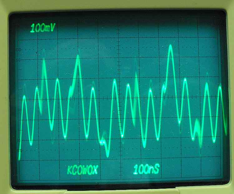
Buttonhook D10. The amplitude is hard to interpret here, I'm going to look at the most consistent sine waves and guess 250 mv's. 250/50= 5. log 5 x 20 = 14db. The schematic calls for 18 db gain so we are in the ballpark. The difference is probably waveform interpretation.
Finally a nice clean signal! This is at the buttonhook of R57. We have gone through the crystal filter and all of the unwanted signals were blocked. All that is left is the desired signal.
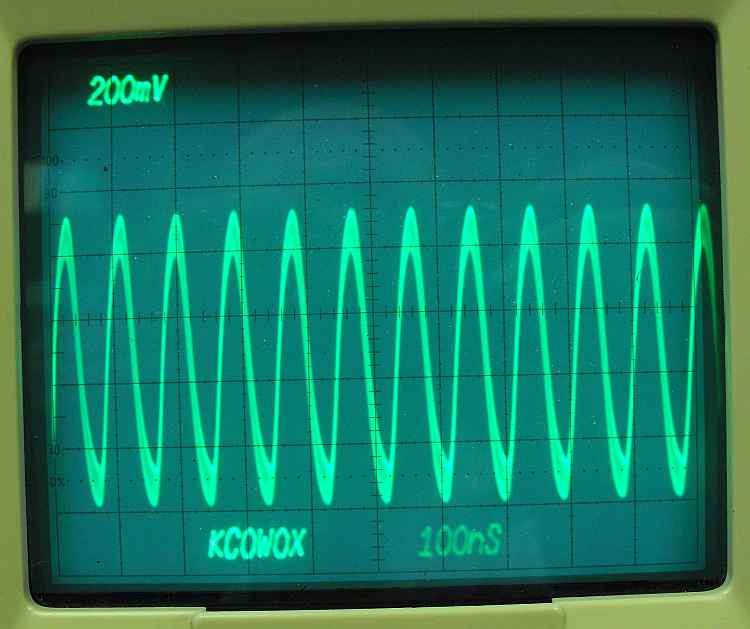
Buttonhook R64. The extra "fuzz" on the signal is the bfo frequency. It's coupled out through the transformer T6. We have 900 mv's out with 100 mv's in. Log of 9 x 20 = 19.08db. The schematic calls for 18.5db so on we go.
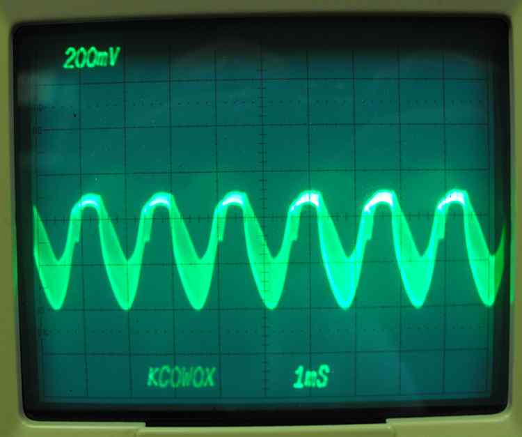
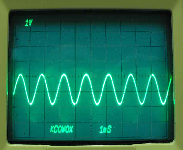
Buttonhook R77. Now we are starting to overdrive the circuitry with the amplitude levels. Notice the the sweep speed is now 1ms/div. What we see here is audio with 11 MHz riding on it. The audio frequency is about 1.6 KHz.
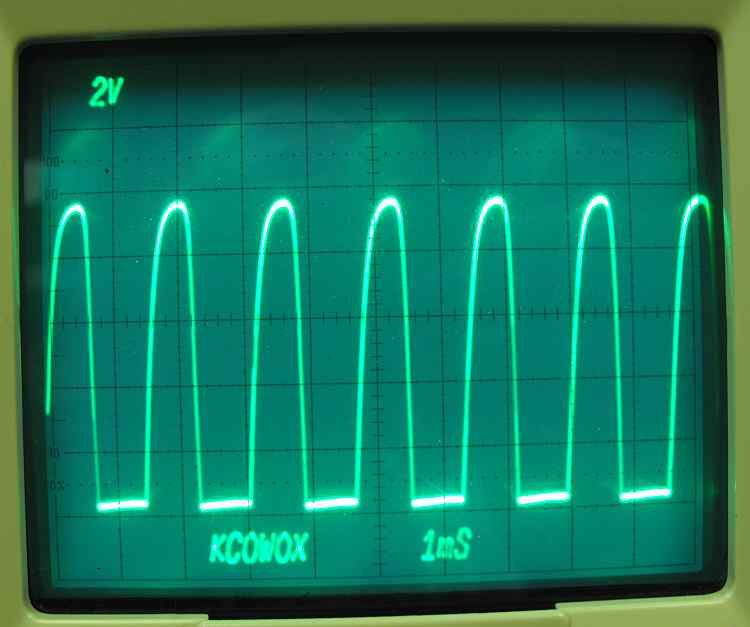
Volume control "hot" wire. Now this is way overdriven. This is the result of way too much signal on the input. Lets change the input signal.
The scope is still on the hot lead on the volume control. The input level has been changed to 1mv rms or 2.8 mv pk-pk.