Photographing the Bitx waveforms
Photographing waveforms in an electronic device can become a complicated process. Especially if you have older equipment. The problems may go away with newer equipment but along with the improvements comes a large price tag. This is the workaround I use.
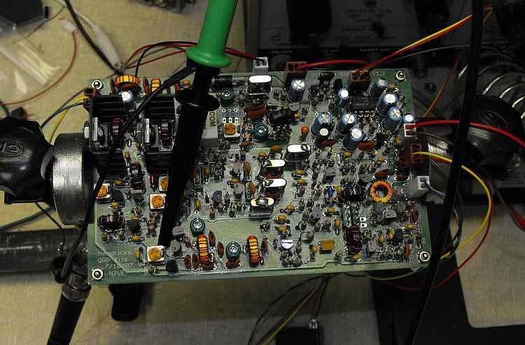
First I probe the board using a x10 probe. This reduces the capacitance I inject into the circuit because of probe capacitance and gives me a 10 megohm input impedance when connected to a scope 1 megohm input. I can't hook directly to the spectrum analyzer because of it's 50 ohm input impedance.
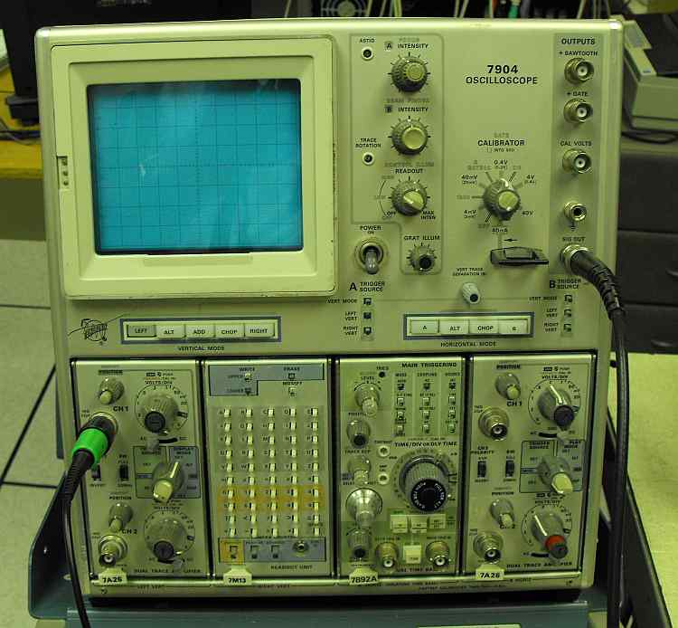
The probe goes to my scope input. I take the signal out of the scope at the SIG OUT connector. Most scopes have this output. At least the older analog ones. This output on my scope is the channel A signal at around 100mv/division. That is, 1 division of vertical deflection will produce a 100mv output. This I run to the spectrum analyzer input.
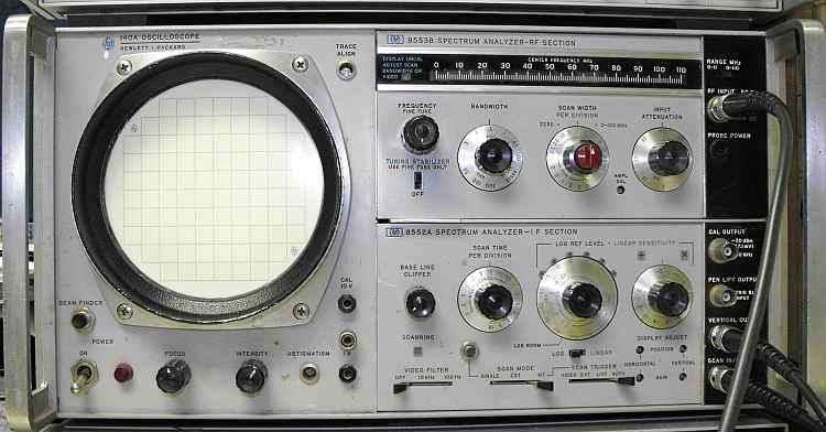
It goes into the RF Input connector. If I am shooting video, I shoot directly from the screen. If I need still pictures, I have to go through one more step. I don't have a storage display for the spectrum analyzer so between slow sweep speeds and camera shutter speeds, I need to run through a storage device to that the picture from. That is what the two cables on the lower are for. One is the vertical output signal and the other is a ramp signal timed with the analyzer horizontal display.
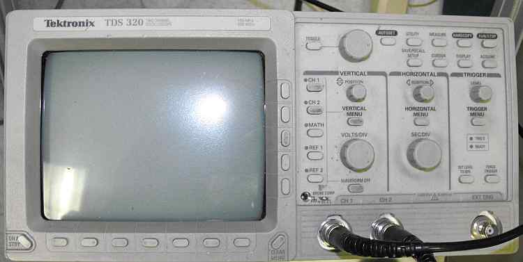
Here I use a digital scope. This gives me a stationary display to photograph. I set it for an X/Y display and connect the horizontal and vertical inputs from the analyzer to it and presto. My photo setup!