Building the Kits and Parts 10 watt linear
part 1 - the resistor installation
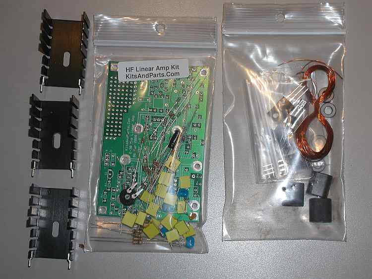
The kit arrived very quickly. Just a few days after I ordered it. I had placed the order almost immediately after the form appeared on the web site. This was order #1 for the kit! Opening it, I could see it was very nicely done. The printed circuit board looked exceptional.
The kit contents
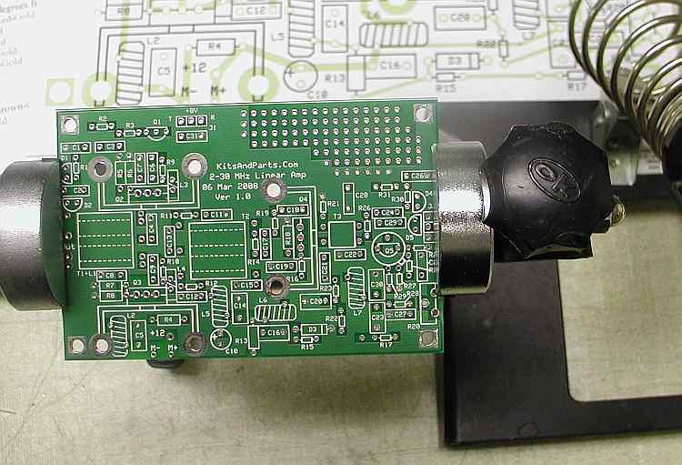
The board
The next step was to print out the assembly instructions from the web site. One thing to notice is that there is detailed directions behind the hyperlinks. These will not print out using the computer print command. I like the added detail though that each link gives. You may need a computer near the assembly work space to use this feature.
I highly recommend printing out the parts list and inventorying the parts. This is a step many of us eliminate, hint, as in me. This caused a little problem when I was installing the resistors. I had an extra one of one value and was short one of another value. I had the right number of resistors but not the correct values. This caused a complete, detailed examination of the board comparing installed values against the boards component layout diagram as the board identifiers were now buried beneath the components. Luckily, I had one of the correct value although it was a carbon comp one, not metal film like what the board was designed for, and it was larger so I have one ugly one installed on my board. I will get the correct value next time I place an order and then replace to one on the board.
To inventory the parts you will need a good magnifying glass and good lighting. The 1/8th watt resistors are difficult to read without magnification. I used my binocular microscope that I have for working with surface mount parts but a good magnifying glass and a strong light will also work very well.
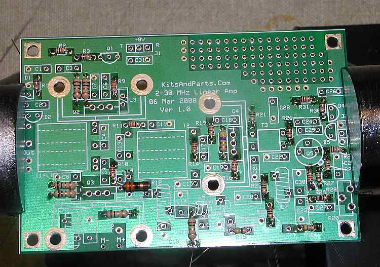
I installed all of the 1/4 watt resistors first as directed by the instructions. After soldering them in, I installed the 1/8th watt resistors. The lead bends need to be very close to the component so just bending them over by hand will work well. Working with the tiny resistors isn't a whole lot different than with surface mount parts. You will need a clean work space and have to handle the parts very carefully. I dropped a resistor and ended up on my hands and knees searching the floor for it. After about 5 minutes, I found it. I used a death grip on them from then on.
I found that soldering on the top of the board worked better than on the bottom. If you solder on the bottom, the body of the component absorbs too much of the heat applied on the bottom of the board and the solder will not wick through the pad to the top properly.
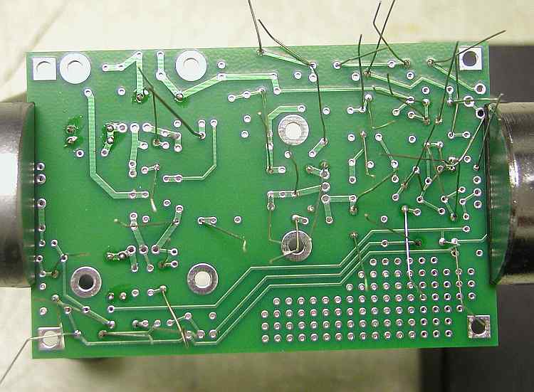
Bottom before the 1/8th watt solder operation.
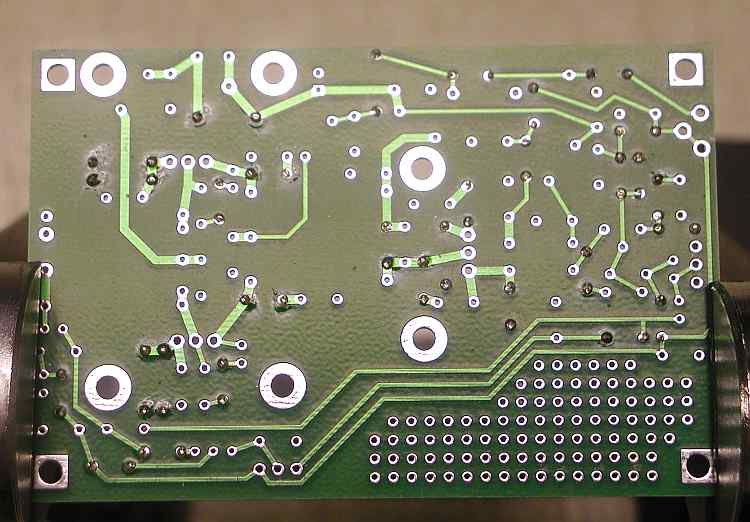
Leads are all clipped and ready to go to part 2 - Winding and installing all of the toroids. The solder flux will be removed after the board is completed.